


Single Source Machine Control
……………………………………………..…...……………….
Power // Flexibility // Ease of Use
21314 Lassen St. Chatsworth, CA 91311 // Tel. (818) 998-2095 Fax. (818) 998-7807 //
www.deltatau.com
^1
HARDWARE REFERENCE MANUAL
^2
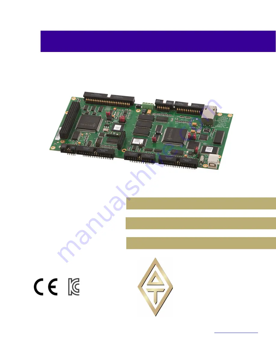
Turbo PMAC Clipper
^3
Turbo PMAC Clipper
^4
4xx-603871-xAxx
^
5
October 17, 2018
DELTA TAU
Data Systems, Inc.
NEW IDEAS IN MOTION …
Summary of Contents for Turbo PMAC Clipper
Page 5: ......
Page 11: ...Turbo PMAC Clipper Connections and Software Setup 11 SPECIFICATIONS Part Number ...
Page 78: ...Turbo PMAC Clipper Hardware Reference Manual Appendix B 78 APPENDIX B SCHEMATICS ...
Page 79: ...Turbo PMAC Clipper Hardware Reference Manual Appendix B 79 ...
Page 80: ...Turbo PMAC Clipper Hardware Reference Manual Appendix B 80 ...
Page 81: ...Turbo PMAC Clipper Hardware Reference Manual Appendix B 81 ...
Page 82: ...Turbo PMAC Clipper Hardware Reference Manual Appendix B 82 ...
Page 83: ...Turbo PMAC Clipper Hardware Reference Manual Appendix B 83 ...
Page 84: ...Turbo PMAC Clipper Hardware Reference Manual Appendix B 84 ...


