DeLorme GPS2058, User Manual
Looking for a reliable User Manual for your DeLorme GPS2058? Look no further! Download the comprehensive manual for free from manualshive.com, providing step-by-step instructions and helpful insights to maximize your experience with this incredible GPS device. Get ready to navigate with confidence and ease.
Share
Download


Reviews:
No comments
Related manuals for GPS2058
Gps tracker
Brand: GPSMileageTracker Pages: 5

NVD-A801
Brand: Alpine Pages: 230

iti 400A
Brand: Mappy Pages: 40

GTM 60
Brand: Garmin Pages: 11
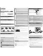
M-Tracer MT500G
Brand: Epson Pages: 2

AmeriGo
Brand: Royal Pages: 80

JV200
Brand: Jivi Pages: 24

CarTrek 600
Brand: CarTrek Pages: 9

CS-TUND09 Toyota Sequoia
Brand: CarShow Pages: 11

CCTR-630
Brand: Carscop Pages: 12

UT01
Brand: UniGuard Pages: 14

GPSM006
Brand: GMC Pages: 28
GPS Tracker
Brand: QBIT Pages: 15

SkySurf V3
Brand: XAiOX Pages: 13

ProBox 3100
Brand: r2p Tracking Pages: 21

TS596A
Brand: Black Box Pages: 2

Road Mentor
Brand: Polstar Pages: 58

RECOVERY
Brand: MVP Pages: 12


