Dell Latitude C840, Service Manual
The Dell Latitude C840 System Information Manual is a comprehensive guide providing in-depth details about the product's specifications, functionalities, and troubleshooting tips. This manual is available for free download at manualshive.com, ensuring convenient access and empowering users with valuable information for optimal usage of their Dell Latitude C840.
Share
Download


Reviews:
No comments
Related manuals for Latitude C840

M520
Brand: Gateway Pages: 4

THINKPAD R50 series
Brand: IBM Pages: 108

ThinkPad i Series 1400
Brand: IBM Pages: 46

ThinkPad 570
Brand: IBM Pages: 3

ThinkPad 380Z
Brand: IBM Pages: 4

ThinkPad 380XD
Brand: IBM Pages: 222

ThinkPad 310E
Brand: IBM Pages: 19

ThinkPad 240
Brand: IBM Pages: 65

ThinkPad 240
Brand: IBM Pages: 67

ThinkPad T60
Brand: IBM Pages: 2

ThinkPad i Series 1400
Brand: IBM Pages: 168

ThinkPad X20
Brand: IBM Pages: 8

TransNote
Brand: IBM Pages: 150

ThinkPad T20
Brand: IBM Pages: 72

M685
Brand: Gateway Pages: 1

Armada 1500C series
Brand: Compaq Pages: 62

Versa 550 Series
Brand: NEC Pages: 128
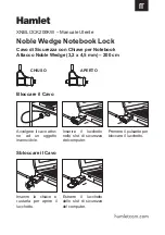
XNBLOCK200KW
Brand: Hamlet Pages: 2


