Dell Latitude 5490, Owner'S Manual
The Dell Latitude 5490 user manual is a comprehensive guide that provides step-by-step instructions for the Setup and Specifications of this high-performance laptop. It is available for free download on manualshive.com, ensuring easy access to all the essential information you need to maximize your experience with this outstanding product.
Share
Download


Reviews:
No comments
Related manuals for Latitude 5490

Toughbook CF-52EKMBDAM
Brand: Panasonic Pages: 2

HUMA H5 V2.1
Brand: Monster Pages: 74

UMM220V14
Brand: UMAX Technologies Pages: 50
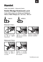
XNBLOCK200KW
Brand: Hamlet Pages: 2

TE69HWP
Brand: Packard Bell Pages: 90

Aspire M3-581T
Brand: Acer Pages: 234

:atitude 3550
Brand: Dell Pages: 57

1720 - Vostro - Core 2 Duo 2.2 GHz
Brand: Dell Pages: 88

LB141
Brand: Bluewave Pages: 11

Extensa 570CD
Brand: Texas Instruments Pages: 85

VGN-AW210J
Brand: Sony Pages: 2

VGN-AW190NAB
Brand: Sony Pages: 2

VGN-A690 - VAIO - Pentium M 1.86 GHz
Brand: Sony Pages: 1

VGN-A290
Brand: Sony Pages: 1

VGN-A270B
Brand: Sony Pages: 1

VGN-A230B - VAIO - Pentium M 1.5 GHz
Brand: Sony Pages: 1

VGN-A230
Brand: Sony Pages: 1

VGN-AR270GA
Brand: Sony Pages: 2


