Dell Inspiron 11-3147 2-in-1, Owner'S Manual
The Dell Inspiron 11-3147 2-in-1 is a sleek and versatile device, perfect for those on the go. To get started quickly, we offer a free Quick Start Manual that you can easily download from our website. Discover all the amazing features and functionalities of this product at manualshive.com.
Share
Download


Reviews:
No comments
Related manuals for Inspiron 11-3147 2-in-1

The Toughbook 31
Brand: Panasonic Pages: 2

Handheld Users
Brand: Palm Pages: 11

MultiBook F14
Brand: ASROCK Pages: 38

P-6831
Brand: Gateway Pages: 168

Solo 1400
Brand: Gateway Pages: 12

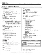
1135-S1552
Brand: Toshiba Pages: 8

1135 S1551 - Satellite - Celeron 2 GHz
Brand: Toshiba Pages: 8

1130-S155
Brand: Toshiba Pages: 8

1135-S125
Brand: Toshiba Pages: 8

1115-S107
Brand: Toshiba Pages: 8

#1203
Brand: Toshiba Pages: 126

/Satellite Pro E40-A
Brand: Toshiba Pages: 163

1130-S155
Brand: Toshiba Pages: 244

1100-S101
Brand: Toshiba Pages: 244

1000 Series
Brand: Toshiba Pages: 246

P505D-S8960
Brand: Toshiba Pages: 4

P505D-S8000
Brand: Toshiba Pages: 4
P505D-S8005
Brand: Toshiba Pages: 4


