Setting Up Your
Dell EMC PowerVault ME4
Series Storage System
© 2019 Dell Inc. or its subsidiaries.
2019-10
1 Before you begin
WARNING:
Before you set up and operate your Dell EMC storage system,
review the safety instructions that came with it.
Unpack storage system equipment
An ME4 Series storage system includes:
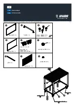
2 Mount the enclosures
WARNING:
Potential injury: chassis is heavy.
• Use at least two people to mount a 2U chassis. Use a mechanical lift to mount a 5U chassis.
• The rack may fall over if allowed to become top-heavy. Load the rack from the
bottom up with the heaviest chassis at the bottom.
Secure the controller enclosure to the rack using the mounting screws located in the
plastic bag.
2U enclosure
1.
Remove the rack mounting rail kit from the box and inspect for damage:
a.
Set each location pin at the rear of the rail into a rear rack post hole. Attach the bracket
to the rear rack post: use the washers and screws supplied. Leave the screws loose.
b.
Extend the rail to fit between the front and rear rack posts, and attach the
bracket to the front rack post using the washers and screws supplied.
c.
Tighten the two clamping screws located along the inside of the rear section of
the rack bracket.
d.
Repeat the above sequence of steps for the companion rail.
2.
Install the enclosure into the rack:
a.
Keeping the enclosure level, carefully insert the chassis slides into the rack rails
and push fully in.
b.
Tighten the mounting screws in the rear kit brackets.
Scan to see how-to videos, documentation,
and troubleshooting information.
Quick Resource Locator
Dell.com/QRL/Storage/ME4series
Figure 1.
2U enclosure
Figure 3.
2U rack mount
Figure 4.
5U rack mount
Figure 2.
5U enclosure
c.
Remove the enclosure until it reaches the end and hard stops approximately 400 mm
(15.75 inches). Tighten the mounting screws on the front of the rail kit bracket.
d.
Return the enclosure to the fully home position.
5U enclosure
The 5U enclosure is shipped without the disks installed. Before mounting, also
remove the rear panel modules to reduce the enclosure weight.
1.
With the preassembled rails at their shortest length, locate the rail location
pins inside the front of the rack, and extend the length of the rail assembly to
position the rear location pins. Ensure the pins are fully inserted in the square or
round holes in the rack posts.
2.
Fully tighten all clamping screws and middle slide locking screws.
3.
Ensure the four rear space clips (not shown) are fitted to the edge of the rack post.
4.
Slide the enclosure until it is fully seated on its rails.
A
B
C
1
2
7
6
8
3
4
5
9
Item Description
Item Description
1
Front rack post - square hole
6
Clamping screw (B)
2
Rear rack post - square hole
7
2U enclosure fastening screw (C)
3
Left rail
8
Clamping screw (B)
4
Rail location pins
9
Exploded view of Ops panel cover, to
show left ear flange fastening screw (A)
5
Locking screw
Item Description
Item Description
1
Fastening screws (A)
6
Middle slide locking screws
2
Left rail
7
Rear left portion of 5U chassis
3
Rear rack post - square hole
8
Front rack post - square hole
4
Clamping screw (B)
9
Front left portion of 5U chassis
shown for reference
5
Rail location pins
A
B
C
8
3
4
1
7
2
5
6
1
4
9
Figure 6.
5U dual–controller cabling (reverse method)
Figure 5.
2U dual–controller cabling: maximum 10 enclosures (reverse method)
0A
1A
2A
3A
0B
1B
2B
3B
0A
1A
2A
9A
0B
1B
2B
9B
5.
Fasten the front and rear of the enclosure using the enclosure fastening screws.
CAUTION:
Once the enclosure is mounted, dispose of the lifting straps.
The straps are not suitable for reuse.
Reinsert the rear panel modules, and install the disks into the drawers accessed from
the front panel
per the instructions in the
Dell EMC PowerVault ME4 Series
Storage System Deployment Guide
.
• Expansion cables (1 per expansion module)
• Optional enclosure bezel with key (1 per
2U enclosure)
• I/O module blank (2U single-controller
storage system only)
• Disk drive blank (if 2U storage system is
not fully populated)
• Appropriate rackmount kit for 2U or 5U
enclosure
• Documentation
• 2U or 5U enclosure
• Power cables (2)
• Separately packaged disk drives (5U
enclosure only)
• Fibre Channel or iSCSI SFP+ transceivers or
cables (1 per host port)
• Host cables (1 per controller module host port)
Develop a configuration plan
Before installing the storage hardware, develop a configuration plan where you can
record host server information, switch information, and network information.
Consider plans for multipath/failover
Redundancy is provided by multipathing, which allows alternate paths if a data path
fails. It is recommended to use multipathing, so that volumes are mapped to ports in
more than one Fibre Channel or iSCSI fabric.
Connect optional expansion enclosures
You can connect a maximum of nine 2U expansion enclosures or three 5U expansion
enclosures to a 2U or a 5U controller enclosure. A 2U controller enclosure can be connected
to a mixture of 2U12 and 2U24 expansion enclosures, or 5U84 only. A 5U controller enclosure
can only be attached to 5U expansion enclosures. Each expansion enclosure includes two
expansion modules.
Figure 5 shows reverse cabling of a dual-controller 2U enclosure and supported
2U expansion enclosures configured with dual expansion modules. Figure 6 shows
reverse cabling of a dual-controller 5U enclosure and supported 5U expansion
enclosures configured with dual expansion modules. Reverse cabling allows any
expansion enclosure to fail—or be removed—while maintaining access to other
enclosures. The middle SAS ports on expansion modules are not used.
3 Connect to the management
network
Each controller’s network port must be connected to a management network.
The network port provides access to management interfaces and is used to send
notifications, SNMP traps, and support data. See figures 7 and 8.
1.
Connect an RJ45 Ethernet cable to the network port on each controller.
2.
Connect the other end of each Ethernet cable to a network that your
management host can access (preferably on the same subnet).
Notes, cautions, and warnings
NOTE
:
Indicates important information that helps you make better use of your
product.
CAUTION:
Indicates potential damage to hardware or loss of data
and tells you how to avoid the problem.
WARNING:
Indicates a potential for property damage, personal
injury, or death.
Figure 7.
2U SAN connections