background image

w w w . d e l l . c o m   |   s u p p o r t . d e l l . c o m

Dell™ XPS™ 400

Owner’s Manual

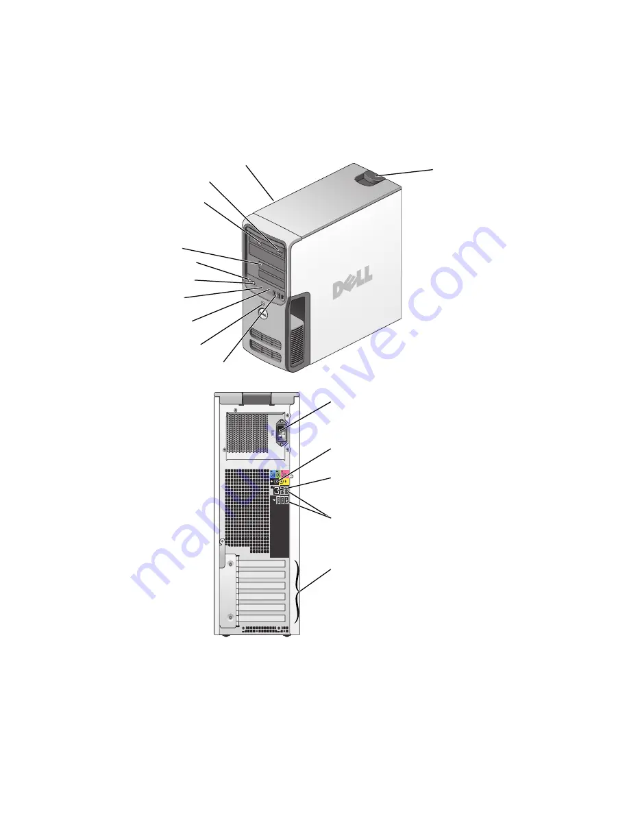
FlexBays (2) for optional
floppy drive or optional 
Media Card Reader

hard-drive activity light

power button

microphone connector

 headphone connector

CD or DVD activity light

CD or DVD eject button

diagnostic lights

USB 2.0 connectors (2)

cover latch release

Service Tag

power connector

USB 2.0 connectors (5)

network adapter

sound-card connectors (5)

card slots for
PCI Express x1 (1), PCI Express x16 (1), 
PCI Express x4 (1), PCI (3)

Model DCTA

Summary of Contents for Dimension 9150

Page 1: ...ive activity light power button microphone connector headphone connector CD or DVD activity light CD or DVD eject button diagnostic lights USB 2 0 connectors 2 cover latch release Service Tag power connector USB 2 0 connectors 5 network adapter sound card connectors 5 card slots for PCI Express x1 1 PCI Express x16 1 PCI Express x4 1 PCI 3 Model DCTA ...

Page 2: ...nc All rights reserved Reproduction in any manner whatsoever without the written permission of Dell Inc is strictly forbidden Trademarks used in this text Dell the DELL logo Dell XPS Inspiron Dimension Precision OptiPlex Latitude PowerEdge PowerVault PowerApp DellNet and PowerConnect are trademarks of Dell Inc Intel and Pentium and Intel SpeedStep are registered trademarks of Intel Corporation Mic...

Page 3: ...8 How to Copy a CD or DVD 18 Using Blank CDs and DVDs 19 Helpful Tips 19 Using a Media Card Reader Optional 20 Connecting Two Monitors 21 Connecting Two Monitors With VGA Connectors 22 Connecting One Monitor With a VGA Connector and One Monitor With a DVI Connector 22 Connecting a TV 23 Changing the Display Settings 23 Setting Up a Home and Office Network 24 Connecting to a Network Adapter 24 Netw...

Page 4: ...ems 38 CD and DVD drive problems 38 Hard drive problems 39 E Mail Modem and Internet Problems 39 Error Messages 41 Media Card Reader Problems 42 Keyboard Problems 42 Lockups and Software Problems 43 The computer does not start up 43 The computer stops responding 43 A program stops responding 43 A program crashes repeatedly 43 A program is designed for an earlier Windows operating system 44 A solid...

Page 5: ...ver 57 Identifying Drivers 58 Reinstalling Drivers 58 Resolving Software and Hardware Incompatibilities 59 Restoring Your Operating System 59 Using Microsoft Windows XP System Restore 60 Using Dell PC Restore by Symantec 61 4 Removing and Installing Parts Before You Begin 63 Recommended Tools 63 Turn Off Your Computer 63 Before Working Inside Your Computer 64 Front View of the Computer 65 Back Vie...

Page 6: ... Panel 93 Drives 93 General Installation Guidelines 94 Hard Drive 94 Removing a Hard Drive 95 Installing a Hard Drive 96 Adding a Second Hard Drive 97 Floppy Drive 99 Removing a Floppy Drive 99 Installing a Floppy Drive 101 Media Card Reader 101 Removing a Media Card Reader 102 Installing a Media Card Reader 104 CD DVD Drive 105 Removing a CD DVD Drive 106 Installing a CD DVD Drive 107 Battery 109...

Page 7: ... Settings 124 Cleaning Your Computer 124 Computer Keyboard and Monitor 124 Mouse 125 Floppy Drive 125 CDs and DVDs 125 Dell Technical Support Policy U S Only 125 Definition of Dell Installed Software and Peripherals 126 Definition of Third Party Software and Peripherals 126 FCC Notices U S Only 126 Class A 127 Class B 127 FCC Identification Information 128 Contacting Dell 128 Index 147 ...

Page 8: ...8 Contents ...

Page 9: ...re Warranty information Terms and conditions U S only Safety instructions Regulatory information Ergonomics information End User License Agreement Dell Product Information Guide NOTE This document is available as a PDF at support dell com How to set up my computer Setup Diagram ...

Page 10: ...d Microsoft Windows License These labels are located on your computer Use the Service Tag to identify your computer when you use support dell com or contact technical support Enter the Express Service Code to direct your call when contacting technical support The Express Service Code is not available in all countries What Are You Looking For Find It Here ...

Page 11: ...s for your operating system and support for Dell 3 5 inch USB floppy drives Intel Pentium M processors optical drives and USB devices DSS is necessary for correct operation of your Dell computer The software automatically detects your computer and operating system and installs the updates appropriate for your configuration To download Desktop System Software 1 Go to support dell com and click Down...

Page 12: ...ocumentation for devices such as a modem Windows Help and Support Center 1 Click the Start button and click Help and Support 2 Type a word or phrase that describes your problem and click the arrow icon 3 Click the topic that describes your problem 4 Follow the instructions on the screen What Are You Looking For Find It Here ...

Page 13: ...tall updated drivers Connect the printer to the computer Load paper and install the toner or ink cartridge Contact the printer manufacturer for technical assistance Printer Cable Your printer connects to your computer with a USB cable Your printer may not come with a printer cable so if you purchase a cable separately ensure that it is compatible with your printer If you purchased a printer cable ...

Page 14: ...ountry To connect to the Internet you need a modem or network connection and an Internet service provider ISP such as AOL or MSN Your ISP will offer one or more of the following Internet connection options Dial up connections that provide Internet access through a telephone line Dial up connections are considerably slower than DSL and cable modem connections DSL connections that provide high speed...

Page 15: ...The New Connection Wizard appears 3 Click Connect to the Internet 4 In the next window click the appropriate option If you do not have an ISP and want to select one click Choose from a list of Internet service providers ISPs If you have already obtained setup information from your ISP but you did not receive a setup CD click Set up my connection manually If you have a CD click Use the CD I got fro...

Page 16: ...ess the eject button on the front of the drive 2 Place the disc label side up in the center of the tray 3 Press the eject button or gently push in the tray To format CDs for storing data to create music CDs or to copy CDs see the CD software that came with your computer NOTE Ensure that you follow all copyright laws when you create CDs A CD player includes the following basic buttons Play Move bac...

Page 17: ...Entertainment and then click Volume Control 2 In the Volume Control window click and drag the bar in the Volume Control column and slide it up or down to increase or decrease the volume For more information on volume control options click Help in the Volume Control window Eject Go to the next track Stop Restart the current chapter Play Fast forward Pause Fast reverse Advance a single frame while i...

Page 18: ...o use Sonic RecordNow for other purposes including creating CDs from audio files on your computer and creating MP3 CDs For instructions see the Sonic RecordNow documentation that came with your computer Open Sonic RecordNow click the question mark icon in the upper right corner of the window and then click the help or tutorial option How to Copy a CD or DVD NOTE If you have a DVD CD RW combo drive...

Page 19: ...manently store large amounts of information however you may not be able to write to the disc again if the disc is finalized or closed during the final stage of the disc creation process Use blank DVD RWs if you plan to erase rewrite or update information on the disc later Helpful Tips Use Microsoft Windows Explorer to drag and drop files to a CD R or CD RW disc only after you start Sonic RecordNow...

Page 20: ...dia Card Reader Optional Use the Media Card Reader to transfer data directly to your computer The Media Card Reader supports the following memory types xD Picture Card SmartMedia SMC CompactFlash Type I and II CF I II MicroDrive Card SecureDigital Card SD MultiMediaCard MMC Memory Stick MS MS Pro ...

Page 21: ... and try again Connecting Two Monitors CAUTION Before you begin any of the procedures in this section follow the safety instructions in the Product Information Guide NOTE If you are connecting two monitors that have VGA connectors you must have the optional DVI adapter If you are connecting two flat panel monitors at least one of them must have a VGA connector If you are connecting a television yo...

Page 22: ...u Begin on page 63 2 Connect one of the monitors to the VGA blue connector on the back of the computer 3 Connect the other monitor to the optional DVI adapter and connect the DVI adapter to the DVI white connector on the back of the computer Connecting One Monitor With a VGA Connector and One Monitor With a DVI Connector 1 Follow the procedures in Before You Begin on page 63 2 Connect the VGA conn...

Page 23: ... or DVI monitor Changing the Display Settings 1 After you connect the monitor s or TV turn on the computer The Microsoft Windows desktop displays on the primary monitor 2 Enable clone mode or extended desktop mode in the display settings In clone mode both monitors display the same image In extended desktop mode you can drag objects from one screen to the other effectively doubling the amount of v...

Page 24: ...etwork device Network Setup Wizard The Microsoft Windows XP operating system provides a Network Setup Wizard to guide you through the process of sharing files printers or an Internet connection between computers in a home or small office 1 Click the Start button point to All Programs Accessories Communications and then click Network Setup Wizard 2 On the welcome screen click Next 3 Click Checklist...

Page 25: ...lick Control Panel 2 Under Pick a category click Performance and Maintenance 3 Under or pick a Control Panel icon click Power Options To immediately activate standby mode without a period of inactivity click the Start button click Turn Off Computer and then click Stand by To exit from standby mode press a key on the keyboard or move the mouse NOTICE If your computer loses power while in standby mo...

Page 26: ... scheme has different settings for starting standby mode or hibernate mode turning off the monitor and turning off the hard drive The Power schemes drop down menu displays the following schemes Always On default If you want to use your computer with no power conservation Home Office Desk If you use your computer as a home or office computer and you require minimal power conservation Presentation I...

Page 27: ...te tab For more information on power management options 1 Click the Start button and click Help and Support 2 In the Help and Support window click Performance and maintenance 3 In the Performance and maintenance window click Conserving power on your computer IEEE 1394 IEEE 1394 is a digital interface that can move large amounts of data between computers and peripheral devices IEEE 1394 is ideal fo...

Page 28: ...bout Your RAID Configuration This section provides an overview of the RAID configuration that you might have selected when you purchased your computer Although several RAID configurations are available Dell offers either a RAID level 0 configuration or a RAID level 1 configuration A RAID level 0 configuration is recommended for high performance gaming and a RAID level 1 configuration is recommende...

Page 29: ...ther drive is also inaccessible Therefore ensure that you perform regular backups when you use a RAID level 0 configuration RAID Level 1 Configuration RAID level 1 uses a data redundancy storage technique known as mirroring When data is written to the primary drive it is then duplicated or mirrored on the other drive A RAID level 1 configuration sacrifices high data access rates for its data redun...

Page 30: ...s to configure RAID hard drive volumes One method uses the Intel RAID Option ROM utility and is performed before you install the operating system onto the hard drive The second method uses the Intel Matrix Storage Manager or Intel Matrix Storage Console and this method is performed after you have installed the operating system and the Intel Matrix Storage Console Both methods require that you set ...

Page 31: ...rate an existing storage configuration to RAID level 0 configuration 1 Set your computer to RAID enabled mode see page 30 2 Press Ctrl i when you are prompted to enter the Intel RAID Option ROM utility 3 Press the up and down arrow keys to highlight Create RAID Volume and press Enter 4 Enter a RAID volume name or accept the default and press Enter 5 Press the up and down arrow keys to select RAID0...

Page 32: ...ss Enter to create the volume 9 Press y to confirm that you want to create the RAID volume 10 Confirm that the correct volume configuration is displayed on the main Intel RAID Option ROM utility screen 11 Use the up and down arrow keys to select Exit and press Enter 12 Install the operating system see Using Microsoft Windows XP System Restore on page 60 Deleting a RAID Volume NOTE When you perform...

Page 33: ...elerator Intel Matrix Storage Manager to launch the Intel Storage Utility NOTE If you do not see an Actions menu option you have not yet set your computer to RAID enabled mode see page 30 3 On the Actions menu select Create RAID Volume to launch the Create RAID Volume Wizard and then click Next 4 On the Select Volume Location screen click the first hard drive you want to include in your RAID level...

Page 34: ... launch the Intel Storage Utility 2 Right click the Volume icon of the RAID volume you want to delete and select Delete Volume 3 On the Delete RAID Volume Wizard screen click Next 4 Highlight the RAID volume you want to delete in the Available box click the right arrow button to move the highlighted RAID volume into the Selected box and then click Next 5 Click Finish to delete the volume Migrating...

Page 35: ...Manager to launch the Intel Storage Utility NOTE If you do not see an Actions menu option you have not yet set your computer to RAID enabled mode see page 30 3 On the Actions menu click Create RAID Volume From Existing Hard Drive to launch the Migration Wizard 4 Click Next on the first Migration Wizard screen 5 Enter a RAID volume name or accept the default 6 From the drop down box select RAID 1 a...

Page 36: ...nager to launch the Intel Storage Utility 2 Right click the hard drive you want to mark as a spare hard drive 3 Click Mark as Spare To Remove Spare Marking From a Spare Hard Drive 1 Right click the spare hard drive icon 2 Click Reset Hard Drive to Non RAID Rebuilding a Degraded RAID Level 1 Configuration If your computer does not have a spare hard drive and the computer has reported a degraded RAI...

Page 37: ...ystem after you have changed your SATA operation settings restore your previous SATA operation settings and retry booting into the operating system Battery Problems CAUTION There is a danger of a new battery exploding if it is incorrectly installed Replace the battery only with the same or equivalent type recommended by the manufacturer Discard used batteries according to the manufacturer s instru...

Page 38: ...VD drive is not listed perform a full scan with your antivirus software to check for and remove viruses Viruses can sometimes prevent Windows from recognizing the drive TEST THE DRIVE Insert another floppy CD or DVD to eliminate the possibility that the original one is defective Insert a bootable floppy and restart the computer CLEAN THE DRIVE OR DISK See page 124 CHECK THE CABLE CONNECTIONS RUN T...

Page 39: ...e stream is interrupted an error occurs Try closing all programs before you write to the CD DVD RW TURN OFF STANDBY MODE IN WINDOWS BEFORE WRITING TO A CD DVD RW DISC Search for the keyword standby in Windows Help RUN CHECK DISK 1 Click the Start button and click My Computer 2 Right click Local Disk C 3 Click Properties 4 Click the Tools tab 5 Under Error checking click Check Now 6 Click Scan for ...

Page 40: ...10 ft or more in length try a shorter one RUN THE MODEM HELPER DIAGNOSTICS Click the Start button point to All Programs and then click Modem Helper Follow the instructions on the screen to identify and resolve modem problems Modem Helper is not available on all computers VERIFY THAT THE MODEM IS COMMUNICATING WITH WINDOWS 1 Click the Start button and click Control Panel 2 Click Printers and Other ...

Page 41: ...he program you want to remove 3 Click the Change or Remove Program icon 4 See the program documentation for installation instructions drive letter IS NOT ACCESSIBLE THE DEVICE IS NOT READY The drive cannot read the disk Insert a disk into the drive and try again INSERT BOOTABLE MEDIA Insert a bootable floppy or CD NON SYSTEM DISK ERROR Remove the floppy from the drive and restart your computer NOT...

Page 42: ...ia Card Reader 6 Click OK to confirm your selection NOTE The Media Card Reader appears as a mapped drive only when it is connected Each of the four Media Card Reader slots are mapped to a drive even if no media is installed If you attempt to access the Media Card Reader when no media is inserted you are prompted to insert media FLEXBAY DEVICE IS DISABLED There is a FlexBay disable option in the BI...

Page 43: ...s in its documentation or on a floppy or CD CHECK THE DIAGNOSTIC LIGHTS See page 53 ENSURE THAT THE POWER CABLE IS FIRMLY CONNECTED TO THE COMPUTER AND TO THE ELECTRICAL OUTLET TURN THE COMPUTER OFF If you are unable to get a response by pressing a key on your keyboard or moving your mouse press and hold the power button for at least 8 to 10 seconds until the computer turns off Then restart your c...

Page 44: ...g your mouse press and hold the power button for at least 8 to 10 seconds until the computer turns off Then restart your computer CHECK THE SOFTWARE DOCUMENTATION OR CONTACT THE SOFTWARE MANUFACTURER FOR TROUBLESHOOTING INFORMATION Ensure that the program is compatible with the operating system installed on your computer Ensure that your computer meets the minimum hardware requirements needed to r...

Page 45: ...y modules see page 74 to ensure that your computer is successfully communicating with the memory Run the Dell Diagnostics see page 56 IF YOU EXPERIENCE OTHER MEMORY PROBLEMS Reseat the memory modules see page 74 to ensure that your computer is successfully communicating with the memory Ensure that you are following the memory installation guidelines see page 74 Your computer supports DDR2 memory F...

Page 46: ... Control Panel and then click Printers and Other Hardware 2 Click Mouse 3 Try adjusting the settings REINSTALL THE MOUSE DRIVER See page 58 RUN THE HARDWARE TROUBLESHOOTER See page 60 CHECK THE NETWORK CABLE CONNECTOR Ensure that the network cable is firmly inserted into both the network connector on the back of the computer and the network jack CHECK THE NETWORK LIGHTS ON THE BACK OF THE COMPUTER...

Page 47: ...les to verify that the computer turns on properly Ensure that the electrical outlet is working by testing it with another device such as a lamp Ensure that the main power cable and front panel cable are securely connected to the system board see page 71 IF THE POWER LIGHT IS STEADY AMBER A device might be malfunctioning or incorrectly installed Remove and then reinstall the memory modules see page...

Page 48: ... See the printer documentation for cable connection information Ensure that the printer cables are securely connected to the printer and the computer see page 13 TEST THE ELECTRICAL OUTLET Ensure that the electrical outlet is working by testing it with another device such as a lamp VERIFY THAT THE PRINTER IS RECOGNIZED BY WINDOWS 1 Click the Start button click Control Panel and then click Printers...

Page 49: ...dware 2 Click Scanners and Cameras If your scanner is listed Windows recognizes the scanner REINSTALL THE SCANNER DRIVER See the scanner documentation for instructions CHECK THE SPEAKER CABLE CONNECTIONS Ensure that the speakers are connected as shown on the setup diagram supplied with the speakers If you purchased a sound card ensure that the speakers are connected to the card ENSURE THAT THE SUB...

Page 50: ...securely inserted into the headphone connector see page 66 ADJUST THE WINDOWS VOLUME CONTROL Click or double click the speaker icon in the lower right corner of your screen Ensure that the volume is turned up and that the sound is not muted CHECK THE MONITOR CABLE CONNECTION Ensure that the graphics cable is connected as shown on the setup diagram for your computer If you are using a graphics exte...

Page 51: ...HE MONITOR If your speaker system includes a subwoofer ensure that the subwoofer is at least 60 cm 2 ft away from the monitor MOVE THE MONITOR AWAY FROM EXTERNAL POWER SOURCES Fans fluorescent lights halogen lamps and other electrical devices can cause the screen image to appear shaky Turn off nearby devices to check for interference ROTATE THE MONITOR TO ELIMINATE SUNLIGHT GLARE AND POSSIBLE INTE...

Page 52: ...52 Solving Problems w w w d e l l c o m s u p p o r t d e l l c o m ...

Page 53: ...re BIOS failure has occurred All four diagnostic lights display solid green and then turn off after the system successfully boots to the operating system Plug the computer into a working electrical outlet Also see Power Problems on page 47 A possible processor failure has occurred If the problem persists contact Dell see page 128 Memory modules are detected but a memory failure has occurred If you...

Page 54: ...re detected If you have two or more memory modules installed remove the modules reinstall one module see page 74 and then restart the computer If the computer starts normally reinstall an additional module Continue until you have identified a faulty module or reinstalled all modules without error If available install properly working memory of the same type into your computer see page 74 If the pr...

Page 55: ...re that the cables are properly connected to the system board from the hard drive CD drive and DVD drive see page 71 If there is an error message on your screen identifying a problem with a device such as the floppy drive or hard drive check the device to ensure that it is functioning properly The operating system is attempting to boot from a device such as the floppy drive or hard drive check sys...

Page 56: ...the Dell Diagnostics loads and the Main Menu screen appears click the button for the option you want 2 If a problem is encountered during a test a message appears with an error code and a description of the problem Write down the error code and problem description and follow the instructions on the screen If you cannot resolve the error condition contact Dell see page 128 NOTE The Service Tag for ...

Page 57: ... drivers such as the keyboard driver come with your Microsoft Windows operating system You may need to install drivers if you Upgrade your operating system Reinstall your operating system Connect or install a new device Tab Function Results Displays the results of the test and any error conditions encountered Errors Displays error conditions encountered error codes and the problem description Help...

Page 58: ... Dell Support website at support dell com provides approved drivers for Dell computers If you install drivers obtained from other sources your computer might not work correctly Using Windows XP Device Driver Rollback If a problem occurs on your computer after you install or update a driver use Windows XP Device Driver Rollback to replace the driver with the previously installed version 1 Click the...

Page 59: ...ed during the operating system setup or is detected but incorrectly configured you can use the Hardware Troubleshooter to resolve the incompatibility To resolve incompatibilities using the Hardware Troubleshooter 1 Click the Start button and click Help and Support 2 Type hardware troubleshooter in the Search field and click the arrow to start the search 3 Click Hardware Troubleshooter in the Searc...

Page 60: ...8 to resolve the problem If that is unsuccessful then use System Restore NOTICE Before you restore the computer to an earlier operating state save and close any open files and exit any open programs Do not alter open or delete any files or programs until the system restoration is complete 1 Click the Start button point to All Programs Accessories System Tools and then click System Restore 2 Ensure...

Page 61: ...e by Symantec only as the last method to restore your operating system PC Restore restores your hard drive to the operating state it was in when you purchased the computer Any programs or files added since you received your computer including data files are permanently deleted from the hard drive Data files include documents spreadsheets e mail messages digital photos music files and so on If poss...

Page 62: ...ually shut down the computer Click Finish and let the computer completely reboot 6 When prompted click Yes The computer restarts Because the computer is restored to its original operating state the screens that appear such as the End User License Agreement are the same ones that appeared the first time the computer was turned on 7 Click Next The System Restore screen appears and the computer resta...

Page 63: ...may require the following tools Small flat blade screwdriver Phillips screwdriver Flash BIOS update program floppy disk or CD Turn Off Your Computer NOTICE To avoid losing data save and close any open files and exit any open programs before you turn off your computer 1 Shut down the operating system a Save and close any open files exit any open programs click the Start button and then click Turn O...

Page 64: ...s have a connector with locking tabs if you are disconnecting this type of cable press in on the locking tabs before you disconnect the cable As you pull connectors apart keep them evenly aligned to avoid bending any connector pins Also before you connect a cable ensure that both connectors are correctly oriented and aligned NOTICE To avoid damaging the computer perform the following steps before ...

Page 65: ...ctivity light The drive light is on when the computer reads data from the CD or DVD drive 3 CD or DVD eject button Press to eject a disc from the CD or DVD drive 4 FlexBay drives 2 Can contain an optional floppy drive or optional Media Card Reader For information on using the Media Card Reader see Using a Media Card Reader Optional on page 20 2 3 10 4 5 9 11 8 6 7 1 12 13 ...

Page 66: ...commended that you use the back USB connectors for devices that typically remain connected such as printers and keyboards 8 power button Press to turn on the computer NOTICE To avoid losing data do not use the power button to turn off the computer Instead perform an operating system shutdown 9 hard drive activity light The hard drive activity light is on when the computer reads data from or writes...

Page 67: ...ine out connector Use the green line out connector to attach headphones and most speakers with integrated amplifiers Microphone connector Use the pink microphone connector to attach a personal computer microphone for voice or musical input into a sound or telephony program Surround connector Use the black surround connector to attach multichannel capable speakers Center subwoofer Center LFE connec...

Page 68: ...g either the computer or the surface on which it is resting 3 Lay your computer on its side with the computer cover facing up 4 Pull back the cover latch release on the top panel 3 network connector To attach your computer to a network or broadband device connect one end of a network cable to either a network jack or your network or broadband device Connect the other end of the network cable to th...

Page 69: ... the three hinge tabs on the bottom edge of the computer 6 Grip the sides of the computer cover and pivot the cover up 7 Lift the cover away and set it aside in a secure location computer cover cover latch release back of computer hinge tabs 3 ...

Page 70: ... e l l c o m Inside View of Your Computer CAUTION Before you begin any of the procedures in this section follow the safety instructions in the Product Information Guide hard drive power supply system board floppy drive CD or DVD drive may not be present on all computers ...

Page 71: ...ector battery socket BATTERY SATA connectors 4 SATA0 SATA1 SATA2 SATA3 IDE drive connector floppy drive connector FLOPPY front panel I O connector password jumper PSWD PCI Express x16 card connector PCI Express x1 card connector clear CMOS jumper RTCRST FlexBay USB connector PCI card connectors PCI Express x4 card connector Serial 2 connector fan card cage connector memory fan connector ...

Page 72: ...rmine the module s capacity NOTE Always install memory modules in the order indicated on the system board The recommended memory configurations are A pair of matched memory modules installed in connectors DIMM_1 and DIMM_2 or A pair of matched memory modules installed in connectors DIMM_1 and DIMM_2 and another matched pair installed in connectors DIMM_3 and DIMM_4 If you install mixed pairs of DD...

Page 73: ...DIMM_1 and DIMM_2 or connectors DIMM_3 and DIMM_4 Addressing Memory With 4 GB Configurations Your computer supports a maximum of 4 GB of memory when you use four 1 GB DIMMs Current operating systems such as Microsoft Windows XP can only use a maximum of 4 GB of address space however the amount of memory available to the operating system is less than 4 GB Certain components within the computer requ...

Page 74: ...your computer s electronic components You can do so by touching an unpainted metal surface on the computer 1 Follow the procedures in Before You Begin on page 63 2 Remove the computer cover see page 68 3 Lay the computer on its side so that the system board is on the bottom of the inside of the computer 4 Press out the securing clip at each end of the memory module connector 5 Align the notch on t...

Page 75: ...e module into the connector until the module snaps into position If you insert the module correctly the securing clips snap into the cutouts at each end of the module 7 Close the computer cover NOTICE To connect a network cable first plug the cable into the network wall jack and then plug it into the computer notches memory module cutouts 2 crossbars notches memory module cutouts 2 crossbars ...

Page 76: ...urface on the computer 1 Follow the procedures in Before You Begin on page 63 2 Remove the computer cover see page 68 3 Press out the securing clip at each end of the memory module connector 4 Grasp the module and pull up If the module is difficult to remove gently ease the module back and forth to remove it from the connector Cards CAUTION Before you begin any of the procedures in this section fo...

Page 77: ...the card from the operating system If you are installing or replacing a PCI Express card see Installing a PCI Express Card on page 82 Installing a PCI Card NOTE Dell offers an optional customer kit for Audigy II and IEEE 1394 PCI add in cards that includes a front mounted IEEE 1394 connector 1 Follow the procedures in Before You Begin on page 63 2 Remove the computer cover see page 68 cardretentio...

Page 78: ... holding it in place b Set the retention mechanism aside in a secure location 5 If you are installing a new card remove the filler bracket to create a card slot opening Then continue with step 7 6 If you are replacing a card that is already installed in the computer remove the card If necessary disconnect any cables connected to the card Grasp the card by its top corners and ease it out of its con...

Page 79: ...he card in the connector and press down firmly Ensure that the card is fully seated in the slot 9 Before you close the card retention door ensure that The tops of all cards and filler brackets are flush with the alignment bar The notch in the top of the card or filler bracket fits around the alignment guide fully seated card not fully seated card bracket caught outside of slot bracket within slot ...

Page 80: ...4 Snap the card retention mechanism into place securing the x16 PCI card 15 Replace the computer cover reconnect the computer and devices to electrical outlets and then turn them on 16 If you installed a sound card a Enter system setup select Integrated Audio Controller and then change the setting to Off b Connect external audio devices to the sound card connectors Do not connect external audio de...

Page 81: ...etting to On b Connect external audio devices to the audio connectors on the back panel of the computer 7 If you removed an add in network connector a Enter system setup select Integrated NIC Controller and then change the setting to On b Connect the network cable to the integrated connector on the back panel of the computer PCI Express Cards Your computer supports One PCI Express x1 card One PCI ...

Page 82: ...If present on your computer rotate the lever on the chassis wall upward 3 Push the two release tabs on the card retention door toward each other and pivot the door open Because the door is captive it will remain in the open position card retention door release tabs 2 filler bracket alignment guide alignment bar lever on chassis wall may not be present on all computers ...

Page 83: ...stalling a new card remove the filler bracket to create a card slot opening Then continue with step 7 6 If you are replacing a card that is already installed in the computer remove the existing card If necessary disconnect any cables connected to the card If your card includes a retention mechanism remove the top of the retention mechanism by pressing the tab and pulling up on the top NOTE For ful...

Page 84: ...en they are connected to a network To guard against electrical shock be sure to unplug your computer from its electrical outlet before installing any cards 9 If you are installing the card into the x16 card connector position the card so that the securing slot is aligned with the securing tab NOTICE Ensure that you release the securing tab to seat the card If the card is not installed correctly yo...

Page 85: ...ler bracket fits around the alignment guide 12 If you removed a card retention mechanism snap it into place securing the x16 PCI E card fully seated card not fully seated card bracket caught outside of slot bracket within slot alignment guide alignment bar card retention door release tab card retention mechanism piano bracket may not be present on all computers ...

Page 86: ...lectrical outlets and then turn them on 14 If you installed a sound card a Enter system setup select Integrated Audio Controller and then change the setting to Off b Connect external audio devices to the sound card s connectors Do not connect external audio devices to the microphone speaker headphone or line in connectors on the back panel 15 If you installed an add in network adapter and want to ...

Page 87: ...s in Before You Begin on page 63 2 Remove the computer cover see page 68 3 If present on your computer rotate the lever on the chassis wall upward card retention door release tabs 2 filler bracket alignment guide alignment bar lever on chassis wall may not be present on all computers ...

Page 88: ...d and gently squeeze in on the sides to release the mechanism from the two tab slots holding it in place b Set the retention mechanism aside in a secure location NOTE For full length PCI E cards if a piano bracket is present on your computer you need to rotate it upward by pressing the tabs on the side of the bracket toward each other card retention door release tab card retention mechanism piano ...

Page 89: ...rd s NOTE For full length PCI E cards if a piano bracket is present on your computer you need to rotate it down into place NOTICE To connect a network cable first plug the cable into the network device and then plug the cable into the computer 10 Replace the computer cover reconnect the computer and devices to electrical outlets and then turn them on 11 Remove the card driver from the operating sy...

Page 90: ...N To guard against electrical shock always unplug your computer from the electrical outlet before removing the cover Removing the Drive Panel 1 Follow the procedures in Before You Begin on page 63 2 Grasping the lever on the sliding plate pull the sliding plate to the right and hold in place NOTE The sliding plate secures and releases the drive panel and helps to secure the drives drive panel slid...

Page 91: ... Panel Insert 1 Turn the drive panel sideways and find the tip of the drive panel insert tab that latches over a tab on the right side of the drive panel 2 Pull the inner tip of the drive panel insert tab away from the drive panel 3 Pivot the drive panel insert out and away from the drive panel 4 Set the drive panel insert aside in a secure location drive panel drive panel insert drive panel inser...

Page 92: ... side of the drive panel insert under the center drive panel tab 2 Rotate the drive panel insert into place and snap the drive panel insert tab over the corresponding tab on the drive panel 3 Ensure that the drive panel insert is correctly seated in the drive panel center drive panel tab drive panel insert tab drive panel drive panel insert ...

Page 93: ...inges 3 Rotate the drive panel toward the computer until the sliding plate lever clicks into place and the drive panel snaps into place on the front panel Drives Your computer supports Two hard drives Serial ATA Two FlexBay drives can contain an optional floppy drive or optional Media Card Reader Two CD or DVD drives drive panel sliding plate sliding plate lever ...

Page 94: ...onnector detaches When connecting and disconnecting a serial ATA cable hold the cable by the connector at each end Hard Drive CAUTION Before you begin any of the procedures in this section follow the safety instructions in the Product Information Guide CAUTION To guard against electrical shock always unplug your computer from the electrical outlet before opening the cover NOTICE To avoid damage to...

Page 95: ...ing Parts 95 Removing a Hard Drive 1 Disconnect the power and hard drive cables from the drive 2 Press in on the tabs on each side of the drive and slide the drive up and out hard drive cable power cable tabs 2 hard drive ...

Page 96: ... to verify that the drive is configured for your computer 3 If your replacement hard drive does not have the hard drive bracket attached remove the bracket from the old hard drive by unsnapping it from the drive 4 Snap the hard drive bracket onto the replacement hard drive 5 Install the hard drive into the computer by sliding the drive into place until you feel it click into place hard drive hard ...

Page 97: ...out installing any software required for the operation of the hard drive Adding a Second Hard Drive CAUTION Before you begin any of the procedures in this section follow the safety instructions in the Product Information Guide CAUTION To guard against electrical shock always unplug your computer from the electrical outlet before opening the cover NOTICE To avoid damage to the drive do not set it o...

Page 98: ... lower hard drive bay until you have removed the hard drive bracket from the inside of the hard drive bay 5 Slide the new hard drive into empty bay until you feel a click NOTE If your replacement hard drive does not have the hard drive bracket attached remove the bracket from the old hard drive by unsnapping it from the drive Snap the bracket onto the new hard drive 6 Gently slide the drive into p...

Page 99: ...turn them on See the documentation that came with the drive for instructions on installing any software required for drive operation Floppy Drive CAUTION Before you begin any of the procedures in this section follow the safety instructions in the Product Information Guide CAUTION To guard against electrical shock always unplug your computer from the electrical outlet before opening the cover NOTE ...

Page 100: ...oppy drive cables from the back of the floppy drive 4 Disconnect the other end of the floppy drive cable from the system board 5 Pull the sliding plate to the right and hold in place 6 Slide the floppy drive out of the floppy drive bay power cable floppy drive cable floppy drive sliding plate sliding plate lever ...

Page 101: ...e way to provide airflow for the fan and cooling vents 6 Close the computer cover NOTICE To connect a network cable first plug the cable in to the network wall jack and then plug it in to the computer 7 Connect your computer and devices to their electrical outlets and turn them on See the documentation that came with the floppy drive for instructions on installing any software required for the ope...

Page 102: ...e your computer discharge static electricity from your body before you touch any of your computer s electronic components You can do so by touching an unpainted metal surface on the computer chassis 1 Follow the procedures in Before You Begin on page 63 2 Lay the computer on its side so that the system board is on the bottom of the inside of the computer 3 Remove the computer cover see page 68 4 R...

Page 103: ...em board see page 71 and route the cable through the clip on the shroud 6 While pushing on the back of the drive remove the Media Card Reader by sliding and holding the sliding plate 7 Replace the drive panel see page 93 8 Replace the computer cover see page 110 Media Card Reader sliding plate sliding plate lever Not present on all computers ...

Page 104: ...hassis 1 Follow the procedures in Before You Begin on page 63 2 Lay the computer on its side so that the system board is on the bottom of the inside of the computer 3 Remove the computer cover see page 68 4 Remove the drive panel see page 90 5 Remove the Media Card Reader from its packaging and ensure that all four screws are included 6 Gently slide the drive into place until you feel a click or f...

Page 105: ...uting clip 10 Replace the computer cover see page 110 CD DVD Drive CAUTION Before you begin any of the procedures in this section follow the safety instructions in the Product Information Guide CAUTION To guard against electrical shock always unplug your computer from the electrical outlet before opening the cover USB cable Media Card Reader Not present on all computers ...

Page 106: ...ing a CD DVD Drive 1 Follow the procedures in Before You Begin on page 63 2 Remove the computer cover see page 68 3 Disconnect the power cable from the back of the drive and the CD DVD drive cable from the back of the drive and the system board power cable CD DVD drive cable system board ...

Page 107: ...drive unpack the drive and prepare it for installation Check the documentation that accompanied the drive to verify that the drive is configured for your computer If you are installing an IDE drive configure the drive for the cable select setting 2 If you are installing a new drive remove the three shoulder screws from the inside of the drive panel insert and attach the screws to the new drive CD ...

Page 108: ...the way to provide airflow for the fan and cooling vents 7 Close the computer cover NOTICE To connect a network cable first plug the cable in to the network wall jack and then plug it in to the computer 8 Connect your computer and devices to their electrical outlets and turn them on See the documentation that came with the drive for instructions on installing any software required for drive operat...

Page 109: ...ent type recommended by the manufacturer Discard used batteries according to the manufacturer s instructions To replace the battery 1 Record all the screens in system setup see page 115 so that you can restore the correct settings in step 10 2 Follow the procedures in Before You Begin on page 63 3 Remove the computer cover see page 68 4 Locate the battery socket NOTICE If you pry the battery out o...

Page 110: ...ctions in the Product Information Guide 1 Ensure that all cables are connected and fold cables out of the way Gently pull the power cables toward you so that they do not get caught underneath the drives 2 Ensure that no tools or extra parts are left inside the computer 3 Close the cover a Pivot the cover down b Press down on the right side of the cover until it closes c Press down on the left side...

Page 111: ...Memory capacities 256 MB 512 MB or 1 GB Minimum memory 512 MB Maximum memory 4 GB BIOS address F0000h Computer Information Chipset Intel 945P DMA channels eight Interrupt levels 24 BIOS chip NVRAM 4 Mb NIC Integrated network interface capable of 10 100 1000 communication System clock 800 or 1066 MHz data rate depending on your processor Video Type PCI Express Audio Type Internal 7 1 channel or PCI...

Page 112: ...tional speed 2 GB s x16 slot bidirectional speed 8 GB s PCI connectors three connector size 120 pins connector data width maximum 32 bits PCI Express connector one x1 connector size 36 pins connector data width maximum 1 PCI Express lane PCI Express connector one x4 connector size 98 pins connector data width maximum 4 PCI Express lanes PCI Express connector one x16 connector size 164 pins connect...

Page 113: ...connector Network adapter RJ 45 connector USB two front panel and five back panel USB 2 0 compliant connectors Audio five back panel connectors for line in line out microphone surround and center Low Frequency Effects LFE channel two front panel connectors for headphones microphone System board connectors Primary IDE drive 40 pin connector on PCI local bus Serial ATA four 7 pin connectors FlexBay ...

Page 114: ...omputer orange light A good connection exists between a 100 Mbps network and the computer off no light The computer is not detecting a physical connection to the network Activity light on integrated network adapter yellow light Blinking indicates activity on the network Diagnostic lights four lights on the front panel see Diagnostic Lights on page 53 Standby power light AUXPWR on the system board ...

Page 115: ...s you are an expert computer user do not change the settings for this program Certain changes can make your computer work incorrectly Environmental Temperature Operating 10 to 35 C 50 to 95 F Storage 40 to 65 C 40 to 149 F Relative humidity 20 to 80 noncondensing Maximum vibration Operating 0 25 G at 3 to 200 Hz at 0 5 octave min Storage 0 5 G at 3 to 200 Hz at 1 octave min Maximum shock Operating...

Page 116: ...ery quickly so you must watch for it to display and then press F2 If you press F2 before you are prompted this keystroke will be lost 4 If you wait too long and the operating system logo appears continue to wait until you see the Microsoft Windows desktop Then shut down your computer see page 63 and try again System Setup Screens The system setup screen displays current or changeable configuration...

Page 117: ...e information about that option and the option s current and available settings By pressing Enter or the left and right arrow keys you can toggle between a primary topic collapsed and subtopics expanded Option Field This field contains information about each option In this field you can view your current settings and make changes to your settings Use the right and left arrow keys to highlight an o...

Page 118: ...tup menu To boot from a USB memory device select the USB device and move it so it becomes the first device in the list Drives Diskette Drive Identifies and defines the floppy drive attached to the FLOPPY connector on the system board as Off USB Internal or Read Only Drives 0 through 3 Identifies the drives attached to the SATA connectors on the system board and lists the capacity for hard drives S...

Page 119: ...t or change the current acoustics mode setting Quiet The hard drive operates at its most quiet setting Suggested The hard drive operates at the level suggested by the drive manufacturer Performance The hard drive operates at its maximum speed NOTE Switching to performance mode will cause the drive heads to move faster causing the hard drive to be noisier However some drives may not see an increase...

Page 120: ... capable modem receives a wake up signal On is the default setting On w Boot to NIC allows the computer to attempt to boot from a network prior to using the boot sequence NOTE Normally the system can be powered up remotely from suspend mode hibernate mode or when powered off When Low Power Mode in the Power Management menu is enabled the computer can only be powered up remotely from Suspend Suspen...

Page 121: ...le device CD Drive The computer attempts to boot from the CD drive If no CD is in the drive or if the CD has no operating system the computer attempts to boot to the next bootable device USB Flash Device Insert the memory device into a USB port and restart the computer When F12 Boot Menu appears in the upper right corner of the screen press F12 The BIOS detects the device and adds the USB flash op...

Page 122: ...he current boot only For example if you are booting to a USB memory key highlight USB Flash Device and press Enter NOTE To boot to a USB device the device must be bootable To make sure your device is bootable check the device documentation Changing Boot Sequence for Future Boots 1 Enter system setup see page 116 2 Use the arrow keys to highlight the Boot Sequence menu option and press Enter to acc...

Page 123: ...ed to pins 1 and 2 3 Close the computer cover see page 110 4 Connect your computer and monitor to electrical outlets and turn them on 5 After the Microsoft Windows desktop appears on your computer shut down the computer see page 63 6 Turn off the monitor and disconnect it from the electrical outlet 7 Disconnect the computer power cable from the electrical outlet and press the power button to groun...

Page 124: ... and devices to electrical outlets and turn them on Cleaning Your Computer CAUTION Before you begin any of the procedures in this section follow the safety instructions in the Product Information Guide Computer Keyboard and Monitor CAUTION Before you clean your computer disconnect the computer from the electrical outlet Clean your computer with a soft cloth dampened with water Do not use liquid or...

Page 125: ... and DVDs NOTICE Always use compressed air to clean the lens in the CD DVD drive and follow the instructions that come with the compressed air Never touch the lens in the drive If you notice problems such as skipping with the playback quality of your CDs or DVDs try cleaning the discs 1 Hold the disc by its outer edge You can also touch the inside edge of the center hole NOTICE To prevent damaging...

Page 126: ...manufacturing process Microsoft Office Norton Antivirus and so on Dell installed peripherals include any internal expansion cards or Dell branded module bay or PC Card accessories In addition any Dell branded monitors keyboards mice speakers microphones for telephonic modems docking stations port replicators networking products and all associated cabling are included Definition of Third Party Soft...

Page 127: ...e interference at your own expense Class B This equipment has been tested and found to comply with the limits for a Class B digital device pursuant to Part 15 of the FCC Rules These limits are designed to provide reasonable protection against harmful interference in a residential installation This equipment generates uses and can radiate radio frequency energy and if not installed and used in acco...

Page 128: ...ree numbers are for use within the country for which they are listed NOTE In certain countries technical support specific to Dell XPS portable computers is available at a separate telephone number listed for participating countries If you do not see a telephone number listed that is specific for XPS portable computers you may contact Dell through the technical support number listed and your call w...

Page 129: ...e 61 City Code 2 E mail Australia au_tech_support dell com E mail Customer Care Australia and New Zealand apcustserv dell com Home and Small Business 1 300 655 533 Government and Business toll free 1 800 633 559 Preferred Accounts Division PAD toll free 1 800 060 889 Customer Care after sales toll free 1 333 55 option 3 Technical Support portables and desktops toll free 1 300 655 533 Technical Sup...

Page 130: ...tional Access Code 00 Country Code 32 City Code 2 Website support euro dell com E mail for French speaking Customers support euro dell com be fr emaildell Technical Support for XPS portable computers only 02 481 92 96 Technical Support for all other Dell computers 02 481 92 88 Technical Support Fax 02 481 92 95 Customer Care 02 713 15 65 Corporate Sales 02 481 91 00 Fax 02 481 92 99 Switchboard 02...

Page 131: ...Small Business toll free 1 800 847 4096 Technical Support med large bus government toll free 1 800 387 5757 Technical Support printers projectors televisions handhelds digital jukebox and wireless 1 877 335 5767 Sales Home Sales Small Business toll free 1 800 387 5752 Sales med large bus government toll free 1 800 387 5755 Spare Parts Sales Extended Service Sales 1 866 440 3355 Cayman Islands Gene...

Page 132: ...e 800 858 2222 Preferred Accounts Division toll free 800 858 2557 Large Corporate Accounts GCP toll free 800 858 2055 Large Corporate Accounts Key Accounts toll free 800 858 2628 Large Corporate Accounts North toll free 800 858 2999 Large Corporate Accounts North Government and Education toll free 800 858 2955 Large Corporate Accounts East toll free 800 858 2020 Large Corporate Accounts East Gover...

Page 133: ...3287 5505 Switchboard Relational 3287 1200 Switchboard Fax Relational 3287 1201 Switchboard Home Small Business 3287 5000 Switchboard Fax Home Small Business 3287 5001 Dominica General Support toll free 1 866 278 6821 Dominican Republic General Support 1 800 148 0530 Ecuador General Support toll free 999 119 El Salvador General Support 01 899 753 0777 Finland Helsinki International Access Code 990...

Page 134: ... 719 Customer Care 0825 338 339 Switchboard 01 55 94 71 00 Sales 01 55 94 71 00 Fax 01 55 94 71 01 Germany Langen International Access Code 00 Country Code 49 City Code 6103 Website support euro dell com E mail tech_support_central_europe dell com Technical Support for XPS portable computers only 06103 766 7222 Technical Support for all other Dell computers 06103 766 7200 Home Small Business Custo...

Page 135: ...dell com Technical Support Dimension and Inspiron 2969 3188 Technical Support OptiPlex Latitude and Dell Precision 2969 3191 Technical Support PowerApp PowerEdge PowerConnect and PowerVault 2969 3196 Customer Care 3416 0910 Large Corporate Accounts 3416 0907 Global Customer Programs 3416 0908 Medium Business Division 3416 0912 Home and Small Business Division 2969 3105 India E mail india_support_d...

Page 136: ...dial within U K only 0870 907 4499 Ireland Sales 01 204 4444 U K Sales dial within U K only 0870 907 4000 Fax Sales Fax 01 204 0103 Switchboard 01 204 4444 Italy Milan International Access Code 00 Country Code 39 City Code 02 Website support euro dell com E mail support euro dell com it it emaildell Home and Small Business Technical Support 02 577 826 90 Customer Care 02 696 821 14 Fax 02 696 821 ...

Page 137: ...56 3490 24 Hour Automated Order Service 044 556 3801 Customer Care 044 556 4240 Business Sales Division up to 400 employees 044 556 1465 Preferred Accounts Division Sales over 400 employees 044 556 3433 Large Corporate Accounts Sales over 3500 employees 044 556 3430 Public Sales government agencies educational institutions and medical institutions 044 556 1469 Global Segment Japan 044 556 3469 Ind...

Page 138: ...o Country Code 853 Technical Support toll free 0800 105 Customer Service Xiamen China 34 160 910 Transaction Sales Xiamen China 29 693 115 Malaysia Penang International Access Code 00 Country Code 60 City Code 4 Website support ap dell com Technical Support Dell Precision OptiPlex and Latitude toll free 1 800 880 193 Technical Support Dimension Inspiron and Electronics and Accessories toll free 1 ...

Page 139: ...ite support euro dell com Technical Support for XPS portable computers only 020 674 45 94 Technical Support for all other Dell computers 020 674 45 00 Technical Support Fax 020 674 47 66 Home Small Business Customer Care 020 674 42 00 Relational Customer Care 020 674 4325 Home Small Business Sales 020 674 55 00 Relational Sales 020 674 50 00 Home Small Business Sales Fax 020 674 47 75 Relational S...

Page 140: ...e support euro dell com E mail support euro dell com no no emaildell Technical Support for XPS portable computers only 815 35 043 Technical Support for all other Dell products 671 16882 Relational Customer Care 671 17575 Home Small Business Customer Care 23162298 Switchboard 671 16800 Fax Switchboard 671 16865 Panama General Support 001 800 507 0962 Peru General Support 0800 50 669 Poland Warsaw I...

Page 141: ...upport Dimension Inspiron and Electronics and Accessories toll free 1800 394 7430 Technical Support OptiPlex Latitude and Dell Precision toll free 1800 394 7488 Technical Support PowerApp PowerEdge PowerConnect and PowerVault toll free 1800 394 7478 Customer Care toll free 1 800 394 7430 option 6 Transaction Sales toll free 1 800 394 7412 Corporate Sales toll free 1 800 394 7419 Slovakia Prague In...

Page 142: ...rt Customer Service and Sales Penang Malaysia 604 633 4810 Spain Madrid International Access Code 00 Country Code 34 City Code 91 Website support euro dell com E mail support euro dell com es es emaildell Home and Small Business Technical Support 902 100 130 Customer Care 902 118 540 Sales 902 118 541 Switchboard 902 118 541 Fax 902 118 539 Corporate Technical Support 902 100 130 Customer Care 902...

Page 143: ...l Technical Support for XPS portable computers only 0848 33 88 57 Technical Support Home and Small Business for all other Dell products 0844 811 411 Technical Support Corporate 0844 822 844 Customer Care Home and Small Business 0848 802 202 Customer Care Corporate 0848 821 721 Fax 022 799 01 90 Switchboard 022 799 01 01 Taiwan International Access Code 002 Country Code 886 Website support ap dell ...

Page 144: ...dell_direct_support dell com Technical Support Corporate Preferred Accounts PAD 1000 employees 0870 908 0500 Technical Support for XPS portable computers only 0870 366 4180 Technical Support direct and general for all other products 0870 908 0800 Global Accounts Customer Care 01344 373 186 Home and Small Business Customer Care 0870 906 0010 Corporate Customer Care 01344 373 185 Preferred Accounts ...

Page 145: ...t toll free 1 800 456 3355 Employee Purchase Program EPP Customers toll free 1 800 695 8133 Printers and Projectors Technical Support toll free 1 877 459 7298 Public government education and healthcare Customer Service and Technical Support toll free 1 800 456 3355 Employee Purchase Program EPP Customers toll free 1 800 695 8133 Dell Sales toll free 1 800 289 3355 or toll free 1 800 879 3355 Dell ...

Page 146: ...146 Appendix w w w d e l l c o m s u p p o r t d e l l c o m ...

Page 147: ...es 43 44 inside view 70 restore to previous state 60 stops responding 43 connectors center LFE 67 headphone 66 IEEE 1394 66 line in 67 line out 67 microphone 66 67 network adapter 68 power 67 sound 67 surround 67 USB 66 68 copying CDs and DVDs 18 cover replacing 110 D Dell Dell Diagnostics 56 support policy 125 support site 11 Dell Premier Support website 9 11 diagnostic lights 53 diagnostics Dell...

Page 148: ...63 recommended tools 63 turning off your computer 63 Internet connection about 14 connection options 14 connection setting up 15 problems 39 K keyboard problems 42 L labels Microsoft Windows 10 Service Tag 10 66 latch release cover 65 lights diagnostic 53 66 front of computer 53 hard drive activity 66 M Media Card Reader installing 101 104 problems 42 removing 101 102 using 20 memory problems 45 m...

Page 149: ...8 CD RW drive 39 computer crashes 43 44 computer stops responding 43 Dell Diagnostics 56 diagnostic lights 53 drives 38 DVD drive 38 e mail 39 error messages 41 general 43 hard drive 39 Internet 39 keyboard 42 Media Card Reader 42 memory 45 modem 39 monitor is blank 50 monitor is hard to read 51 mouse 45 problems continued network 46 power 47 power light conditions 47 printer 48 program crashes 43...

Page 150: ...al support policy 125 transferring information to a new computer 28 troubleshooting Dell Diagnostics 56 diagnostic lights 53 Hardware Troubleshooter 59 Help and Support Center 12 restore to previous state 59 60 tips 37 TV connect to computer 21 23 U USB booting to devices 121 connectors 66 68 V vents 66 front panel 66 volume adjusting 49 W warranty 9 Windows XP Device Driver Rollback 58 Files and ...

Reviews: