background image

HS-1300 

HD 6 CHANNEL 

PORTABLE VIDEO 

STREAMING STUDIO 

Summary of Contents for EPB-1340

Page 1: ...HS 1300 HD 6 CHANNEL PORTABLE VIDEO STREAMING STUDIO...

Page 2: ...ting 13 Wipe Transition Selection 13 Program Preview Source Row 14 Transition Effect 15 Audio Control 16 2 3 MONITOR CONTROL PANEL 16 CHAPTER 3 NETWORK SETUP 19 3 1 SWITCHER SETUP WITH A WINDOWS COMPU...

Page 3: ...FIRMWARE UPDATE PROCEDURE 79 GPI CONNECTION 80 TALLY OUTPUTS 81 FREQUENTLY ASKED QUESTIONS 82 DIMENSIONS 83 SPECIFICATIONS 84 SERVICE AND SUPPORT 87 Disclaimer of Product and Services The information...

Page 4: ...this unit where the power cord will be walked on rolled over or otherwise stressed 9 If an extension cord must be used with this unit make sure that the total of the ampere ratings on the products plu...

Page 5: ...ird party software installations which are not required by our computer systems are not covered under warranty All mail or transportation costs including insurance are at the expense of the owner All...

Page 6: ...nserve natural resources and ensure that it is recycled in a manner that protects human health and the environment For more information about where you can drop off your waste equipment for recycling...

Page 7: ...the multi view The Multi view includes all the input sources as well as preview and program 1 1 Features Simultaneous Live Streaming Recording Broadcast quality HD SD H 264 network streaming Support d...

Page 8: ...8 1 2 System Diagram...

Page 9: ...2 11 Tally Signal Output 5 HD SDI Video Input 1 4 12 USB Firmware Upgrade Port 6 HD SDI Video Output 1 2 13 Stream Port 7 HDMI Video Output 1 3 1 User Memory Function Keys 6 Background Transition GRAB...

Page 10: ...the live show Video Input Modules The HS 1300 is equipped with six video input channels Connect the respective video sources to these video input channels 4 HDMI Video Input 1 2 The Video Input set in...

Page 11: ...em setup using this port 11 Tally Signal Output Sends Red and Green tally signals to each channel Red indicates On Air and Green indicates next camera source 12 USB Firmware Upgrade Port Connect the U...

Page 12: ...opened menu item to the default values Menu Control Menu Control Press the MENU button in the HS 1300 function section to enter the System Configuration Menu Press the UP DOWN LEFT and RIGHT arrow bu...

Page 13: ...P Effect PIP enables the PIP key mode PIP LITE enables the PIP LITE key mode Background Transition GRAB TRANS BG enables Background Transition between Program Preset GRAB grabs the current Program vid...

Page 14: ...ve channel this is the live output The active channel will appear as the Program Output You can switch or CUT from one video source to another directly on the Program row You will see the multi view P...

Page 15: ...PVW TRANS Transition shown on PVW only MIX This button enables MIX transition effect WIPE This button enables WIPE transition effect The WIPE button must be selected when a wipe effect transition bet...

Page 16: ...s it can go the transition between sources is complete The T Bar has indicators next to it which light when the transition is complete Audio Control Headphone Socket 6 3mm Stereo Headphone Socket for...

Page 17: ...Colour Bars Press again to return to the previously selected video input ZOOM This feature is designed for use with HD SDI and HDMI sources above 720p resolution Press this button to zoom in to the v...

Page 18: ...ideo recording STREAM Press the STREAM button to start video streaming SD Card Slot Insert an SD card into the SD card slot for video recording Note Do not remove SD card while it is being written as...

Page 19: ...m the factory the HS 1300 will initially have a static IP address of 192 168 100 101 The unit can be directly connected to a Windows based computer using an RJ 45 ethernet cable The following set up s...

Page 20: ...built in IP finder which is designed for PC with multiple Ethernet cards or DHCP network environment Please note IP finder can only find devices that are on the same network domain as the PC If you c...

Page 21: ...gional office To create this simple dedicated HS 1300 IP network you will need An IP router which can assign give IP addresses Two RJ 45 patch leads Windows 7 8 10 laptop or PC The IP router Administr...

Page 22: ...using the web browser and the router s new IP address 192 168 100 1 11 Use the router s LAN Setup or Configure LAN option again within this option there should be another option called Address Reserva...

Page 23: ...tions on the HS 1300 When delivered from the factory the default static IP settings should be Addr Mode Static a manually set IP address that does not change even after power cycling the HS 1300 unit...

Page 24: ...lack Effect Type Clip Wipe Mix Wipe Effects Wipe Wipe Effect Presets Soft Border Softness Width Border Width Border Luma Border Color Luma Sat Border Color Saturation Hue Border Color Hue Position X H...

Page 25: ...chroma key ranging from 0 to 355 Luma Parameter for luma of the chroma key ranging from 0 to 100 K Range Setting the range of colors that match the background color to be keyed ranging from 0 to 360...

Page 26: ...P Position Border Luma PIP Border Luma Sat PIP Border Color Saturation Hue PIP Border Color Hue Width PIP Border Width Crop Left Left Edge of the Crop Right Right Edge of the Crop Size Size of the Cro...

Page 27: ...nput 6 Input 5 Input 4 Input 3 Input 2 Input 1 OFF 4 Input 6 Input 5 Input 4 Input 3 Input 2 Input 1 OFF 5 Input 6 Input 5 Input 4 Input 3 Input 2 Input 1 OFF 6 Input 6 Input 5 Input 4 Input 3 Input 2...

Page 28: ...t label is followed by information which describes the input as still live or frozen image ON OFF Trns Lab Turn the background of the label from a solid colour to transparent ON OFF Stills Load Still...

Page 29: ...clip Clear Clip Clear the loaded clip Delete Clip Remove the clip from the memory location Setup Standard 1080i 50 Resolution Selections from 1080i 50 59 94 60 720p 60 59 94 50 Save Setup Saves the s...

Page 30: ...der Luma 100 Sat 80 Hue 178 Position X 0 Y 0 Matte Luma 100 Sat 80 Hue 0 Ip Addr 192 168 100 101 Basic Mode Start Transition M E 60 DSK 60 FTB 60 Wipe Effects Wipe 1 Soft 0 Width 0 Transition The tran...

Page 31: ...nput 3 Mask Left 0 Right 0 Top 0 Bot 0 Keyer Control There are three keying modes available Linear Luma and Chroma After the keying mode is chosen if only one source is enabled for the keyer select th...

Page 32: ...ttom edge of the keyer mask Chroma In this option the user will be able to find all the parameters needed to perform chromakeying of the green backdrop Advanced Mode Basic Mode Chroma Keyer Key 1 Key...

Page 33: ...chroma mode Left Left sets the left edge of the Chroma keyer mask Right Right sets the right edge of the Chroma keyer mask Top Top sets the top edge of the Chroma keyer mask Bottom Bottom sets the bo...

Page 34: ...he right edge of the P in P window Size Adjusts the P in P window crop size Top Adjusts the position of the top edge of the P in P window Bot Adjusts the position of the bottom edge of the P in P wind...

Page 35: ...Lite In this sub option the user is allowed to switch between FINE and NORMAL modes In FINE mode the parameters X can be fined tuned with step size 0 1 In NORMAL mode the parameters X is adjusted wit...

Page 36: ...de Outputs Output Sdi 1 Pgm Sdi 2 Input 2 HDMI 1080P Audio Mode On Src Follow Sdi 1 On Sdi 2 On HDMI On Tally Mode Audio Mixer GPI Out Off Mode Pulse Width 1 Input 1 Delay 0 MultiViewer AutoNum Off La...

Page 37: ...r level or pulse The pulse width can also be configured in the sub option Width 1 9 GPI out can then be assigned to one of Inputs 1 6 and the delay can be set to between 0 and 99 This feature could be...

Page 38: ...c memory location The user should determine the source of the still image first The available sources are listed below Input 6 Input 5 Input 4 Input 3 Input 2 Input 1 To complete the save the user can...

Page 39: ...bnail Clip 1 shows the next clip To clear the loaded clip from the buffer simply select Clear Clip To remove clip from a memory location select Delete Clip Setup In the Setup menu the user can change...

Page 40: ...d version of the OSD menu Auto Save When enabled your last settings will be automatically saved before the machine is shut down At the next boot the machine will automatically load the last saved sett...

Page 41: ...how to acquire the NVS 31 IP address Finding the NVS 31 s current IP address You must first know your NVS 31 device s IP address to access the Web User Interface Datavideo provides a free Windows bas...

Page 42: ...chosen make sure to manually assign an IP address to your PC before making attempts to connect to the NVS 31 5 2 Web User Interface By now we have obtained the IP addresses of the computer and the NV...

Page 43: ...rce Audio Source Resolution and Frame Rate will be displayed in a table at the bottom of the page Encoder The NVS 31 provides the user with two encoders so that you can stream and record videos with d...

Page 44: ...rame Rate Select the Frame Rate after the resolution is selected Same as Input 60 00 50 00 30 00 25 00 20 00 15 00 10 00 5 00 1 00 Profile Profile sets the H 264 encoding profile for your stream The a...

Page 45: ...reams and records simultaneously sum of the stream and record video bitrates should not exceed 12Mbps When streaming the NVS 31 converts video into data which are sent across an IP network High bitrat...

Page 46: ...select the size of the crop Record The Record Settings page of the Web User Interface allows you to set the record settings for the NVS 31 device The parameters on the Record page are described as fol...

Page 47: ...files Streaming The NVS 31 provides RTSP and RTMP streaming protocols for use on Adobe Media Servers Wowza Media Servers software video players such as QuickTime and VLC or any of the popular Content...

Page 48: ...48 As soon as the stream is started successfully you will be able to see the RTSP view link Play URL displayed as shown in the diagram below To view the stream open the Play URL in VLC Video Player...

Page 49: ...L rtsp 192 168 1 151 8000 live and then click the Play button to open the view window RTMP Mode In RTMP mode the NVS 31 can only send one data stream to one CDN or media server that supports the RTMP...

Page 50: ...e is configured TS Mode In MPEG transport stream mode the NVS 31 can send stream data directly to the viewer On the streaming setup page select the Encoder Source first and then enter the TS IP addres...

Page 51: ...31 on a fixed IP An example of Static IP mode configuration is provided below Static IP 192 168 1 60 Subnet Mask 255 255 255 0 Default Gateway 192 168 1 254 Primary DNS 192 168 1 1 Secondary DNS 8 8...

Page 52: ...e firmware you must first click the Browse button to search for the firmware file on the disk Please note that if the device is recording or streaming you have to turn the features off in order to per...

Page 53: ...itself after the firmware is successfully updated Time Setting Enter the device s time setting for recording purpose Specify your time server in the NTP field System Related Click the Restore to Defau...

Page 54: ...P JPG PNG and PIC Minimum resolution is 1280 x 720 Independent exported still pictures in BMP format Please follow the steps below to set up the system before installing the software First connect the...

Page 55: ...55 4 Click Install 5 When you see the safety warning requesting for permission to allow an unknown publisher to make changes to the PC please click Yes to continue...

Page 56: ...56 6 Wait for the installation to finish 7 After the setup is complete you will see the following window click Finish to launch SwitcherImageImEx immediately...

Page 57: ...57 8 After the setup is finished a shortcut will be created in Start Menu Programs datavideo tools SwitcherImageImEx 9 Click SwitcherImageImEx to open the program...

Page 58: ...e network as the device 2 If the available device is scanned and found the connection will be automatically established After the connection is successfully established the Connect Status will show Co...

Page 59: ...following interface will be displayed to allow you to crop or enlarge the picture Crop Size Select the right crop Resize Image You will be allowed to select two sizes large 1080 or small 720 and zoom...

Page 60: ...test software version can be downloaded from the product page To update the software it is recommended to remove the existing program first Click Start Menu Programs datavideo tools Uninstall to remov...

Page 61: ...Transition Effect The HS 1300 allows you to generate the stinger transition effect To do this the user should first load the clip saved on the machine to the CH6 window of the Multiview screen first...

Page 62: ...ll 6 Live Crosspoint 1 Input 1 2 Input 2 3 Input 3 4 Input 4 5 Input 5 6 Input 6 6 Move to the Freeze option and set CH6 to Live or Still Importing the Clip for Stinger Transition Effect from the PC O...

Page 63: ...s been successfully established you will be able to see the network information of your switcher Select Import Export from the yellow menu options The clip number allows you to select a location where...

Page 64: ...en start After the import is complete the progress dialog will be automatically closed Note Clip Conversion and Clip Import have progress dialogs that show progress number of frames done These dialogs...

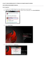
Page 65: ...65 2 The Render Queue will be displayed in the bottom pane...

Page 66: ...list and select PNG Sequence 4 Click the Channels dropdown list and select the RGB Alpha option 5 Click Output To and then change the location where your files are rendered Click Render after that Th...

Page 67: ...ncoder CC 1 Click Composition Add to Media Encoder Queue or alternatively you can also click File Export Add to Media Encoder Queue 2 Click blue fonts in Format Preset fields to open the Export Settin...

Page 68: ...Click the Format dropdown list and then select PNG 4 Click the Preset dropdown list and select PNG Sequence with Alpha 5 Make sure Export As Sequence and Include Alpha Channel are checked and then cli...

Page 69: ...create the Stinger Transition Effects in addition to being creative there are a few things that you need to take into account of 1 Length limit of the stinger transition animation The length of a goo...

Page 70: ...steps below will allow you to preview the keyer effect on the Multiview by simply pressing KEYER PGM or KEYER PVW buttons 1 Set up studio equipment including lights and the backdrop Green Blue 2 Press...

Page 71: ...e final image 7 Chroma Key setting is complete Remarks The HS 1300 is equipped with auto chromakeying function so if after following the above steps a clean chromakeying effect cannot be achieved you...

Page 72: ...Range defines a color range close to the color green of the studio backdrop Key Foreground adjusts the opaqueness and transparency Key Background adjusts the chromakey performance to achieve perfect c...

Page 73: ...presets from to the PC In this section we will show you how you can import and export these user memory presets step by step Export Import User Memory Preset to from the PC 1 On the Switcher Image Imp...

Page 74: ...ort a user settings file 4 To export simply click Export and the following window will open select a preset number to export the user settings to the PC in mem file Click Export User to open the file...

Page 75: ...ress the MENU button to open the OSD menu on the Multiview display 2 Open the User Mems menu option as shown below User Mems Load Mem Memory 13 Load Save Mem Memory 13 Save Load Clip Load Clip 0 Thumb...

Page 76: ...ored within the switcher s non volatile memory Main Options Sub Options Parameters Parameters MAIN ADJUST BRIGHTNESS 0 100 CONTRAST 0 100 SHARPNESS 0 100 SATURATION 0 100 TINT 0 100 BACK LIGHT 0 100 N...

Page 77: ...LOR sub menu To access the selected color setting press ENTER again Use the Up Down buttons to navigate the available color settings You can choose 7500 9300 6500 USER COLOR 7 3 Information The System...

Page 78: ...hich will return all the settings of the monitor to the factory defaults To reset the monitor press the MENU button and then use the UP Down button to navigate to FACTORY RESET option Press ENTER agai...

Page 79: ...le x 1 Once started the update process should not be interrupted in any way as this could result in a non responsive unit 1 Locate the FW Upgrade USB port on the front panel of the HS 1300 2 Insert th...

Page 80: ...ower is supplied by the HS 1300 and is less than 5V DC This GPI socket can also be used as a socket to trigger record or playback events with other equipment such as the Datavideo HDR 70recorder SAFET...

Page 81: ...w 1 Open collector output Tally output of input video Preview 1 4 RCOM GND Ground Ground 5 Program 4 Open collector output Tally output of input video Program 4 6 Program 2 Open collector output Tally...

Page 82: ...y am I seeing blurry images while the video is being streamed over the RTSP protocol 1 The maximum streaming resolution offered on the NVS 31 is 1080p60 so try viewing the streamed video on another co...

Page 83: ...83 Dimensions All measurements in millimetres mm...

Page 84: ...MI OUT 1 2 3 are fixed to PGM Audio Indicator on Multi view Y output 2CH Streaming 1 x RJ 45 100 1000M Ethernet Storage 1x SD Card Slot Supports SD SDHC and SDXC card UHS I Class 10 highly recommended...

Page 85: ...ream Keyers 2 M E Keyer PIP Downstream Keyers 2 Linear Luma Keyers 4 Chroma Keyers 2 M E Keyer PIP Pattern Generators Color Bar PIP 1 XPT Y Frame store Any Input can be used as Frame store 8 Still fra...

Page 86: ...treaming RTMP Publish Control Web browser UI for configuration and control Socket commands Recording File System FAT exFAT Recording File Format MP4 Setting Control Web UI for system configuration and...

Page 87: ...Oct 19 2018 Version E5 http www resource datavideo com manuals Datavideo_HS 1300 pdf...

Reviews: