Dataradio Integra-TR, Technical Manual
The Dataradio Integra-TR is a cutting-edge communication device designed for seamless data transmission. For detailed guidance on operation and functionality, the Technical Manual is available for free download from manualshive.com. This comprehensive manual provides users with step-by-step instructions to optimize the performance and features of their Integra-TR device.
Share
Download


Reviews:
No comments
Related manuals for Integra-TR

Hotwire 7985
Brand: Paradyne Pages: 122

Hotwire 7976
Brand: Paradyne Pages: 24

COMSPHERE 3920PLUS Series
Brand: Paradyne Pages: 285

COMSPHERE 3821PLUS
Brand: Paradyne Pages: 28
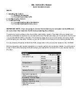
DSL-302G - 8 Mbps DSL Modem
Brand: D-Link Pages: 11

WisGate Edge Lite 2 RAK7268V2
Brand: RAK Pages: 9

GSM35
Brand: Real Time Devices Pages: 33

882?EVDO?XXX
Brand: CalAmp Pages: 62

DMD20 LBST
Brand: Radyne Pages: 306

M13
Brand: LG Pages: 21

VL600
Brand: LG Pages: 40

LXU-800
Brand: LG Pages: 63

SmartThinQ LCW-003
Brand: LG Pages: 353

ThinQ Wi-Fi MODEM
Brand: LG Pages: 16

SmartThinQ LCW-005
Brand: LG Pages: 11

RD-17
Brand: Nokia Pages: 15

A002ZT
Brand: Zte Pages: 128

Courier V.34
Brand: US Robotics Pages: 245


