background image


DS2100N 


QUICK REFERENCE GUIDE 
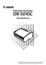


Figure A 


10

9

8

Warning and Device Class Labels

"POWER ON" LED 

Mounting Holes 

"READY" LED 

"TRIGGER" LED 

"COM" LED 

"STATUS" LED 

Push Button 

7

Laser Beam Output Window 

"GOOD" LED 

Accessory Mounting Holes 

11


NOTE 

This manual illustrates a Stand Alone application. For other types of installations, such as 
ID-NET™, Pass-Through, Multiplexer Layout, etc. and for a complete scanner configuration using 
Genius™ configuration program, refer to the DS2100N Reference Manual available on the CD. 
This manual is also downloadable from the Web at 

www.automation.datalogic.com/ds2100n


7

3

4

5

9

10

11

Summary of Contents for DS2100N

Page 1: ...cessory Mounting Holes 11 NOTE This manual illustrates a Stand Alone application For other types of installations such as ID NET Pass Through Multiplexer Layout etc and for a complete scanner configur...

Page 2: ...Handbuches ist auch verf gbar Adresse www automation datalogic com E En Internet est n disponibles las versiones actualizadas de los drivers y documentaci n de este producto Tambi n est disponible la...

Page 3: ...V Power Reference Outputs Earth Protection Earth Ground O1 Output 1 O1 Output 1 Inputs O2 Output 2 V Power Source External Trigger O2 Output 2 I1A External Trigger A polarity insensitive Auxiliary In...

Page 4: ...GND Power supply input voltage 1 CHASSIS Cable shield connected to chassis 18 I1A External Trigger A polarity insensitive 19 I1B External Trigger B polarity insensitive 6 I2A Input 2 A polarity insen...

Page 5: ...Positioning with Mounting Bracket 2 When mounting the DS2100N take into consideration these three ideal label position angles Skew 10 to 30 Tilt 0 and Pitch 0 Assure at least 10 Minimize Minimize Fig...

Page 6: ...NO READ result During the reader startup reset or restart phase all the LEDs blink for one second On the back of the reader near the cable the POWER ON LED indicates the laser scanner is correctly po...

Page 7: ...Y GOOD TRIGGER COM STATUS Figure 6 X PRESS Interface Auto Setup Function The procedure is as follows A place the desired barcode on the scanline B enter the AutoSetup function the laser turns on and t...

Page 8: ...assumes scanner connection to a CBX100 500 Genius running on a laptop computer is connected to the scanner auxiliary port through the CBX100 500 9 pin connector To communicate with the scanner Genius...

Page 9: ...r Presence Sensor using I1A and I1B inputs The Automatic operating mode does not require connection to an external Presence Sensor When working in this mode the reader is continuously scanning while t...

Page 10: ...ation as follows Saving the configuration to disk Switching to Advanced mode Sending the configuration to the scanner 3 After sending the configuration to the scanner you have completed the configurat...

Page 11: ...tton to enter the Test mode function Once entered the Bar Graph on the five LEDs is activated and if the scanner starts reading barcodes the Bar Graph shows the Good Read Rate In case of no read condi...

Page 12: ...g this option it is possible either to start a new scanner configuration or to open and modify an old one The desired parameters can be defined in the following window similar to the MS Explorer Figur...

Page 13: ...m 0 1 3 2 10 6 in 4 5 7 8 9 0 20 40 60 80 100 120 140 160 180 200 220 240 260 mm 280 11 300 12 0 20 mm 8 mils 0 50 mm 20 mils 0 30 mm 12 mils 0 35 mm 14 mils DS2100N 2200 High Resolution CONDITIONS Op...

Page 14: ...140 160 180 200 220 240 260 mm 120 100 80 60 40 20 0 20 40 60 80 100 120 mm 280 11 300 12 0 15 mm 6 mils 0 20 mm 8 mils 0 30 mm 12 mils 0 50 mm 20 mils DS2100N 2204 High Performance High Resolution CO...

Page 15: ...ntinuous max 130 mA pulsed max 1V max at 10 mA 80 mW max at 45 C ambient temperature OPTICAL FEATURES Light Source Semiconductor laser diode Wavelength In the range 630 to 680 nm Safety Class Class 2...

Page 16: ...7 0 58 M 4 n 4 1 29 32 7 mm inch 68 2 68 46 1 81 SETUP LEARN TEST READY GOOD TRIGGER COM STATUS DS2100N XPRESS INTERFACE The quote refers to the scan line Figure 10 DS2100N Overall Dimensions 9 4 2 7...

Page 17: ...0012 Calderara di Reno MADE IN ITALY www datalogic com Figure 12 Warning and Device Class Labels FCC COMPLIANCE Modifications or changes to this equipment without the expressed written approval of Dat...

Page 18: ...DS2100N QUICK GUIDE 18 PATENTS This product is covered by one or more of the following patents U S patent 5 992 740 European patent 789 315 B1...

Page 19: ...er States relating to electromagnetic compatibility and product safety Bas e sur la l gislation des Etats membres relative la compatibilit lectromagn tique et la s curit des produits ber die Ann herun...

Reviews: