


CBX100
Installation Manual
The CBX100 is a connection box which can be used as an accessory to
facilitate system connections for installation and device replacement of
several Datalogic family reading devices.
System cabling is made through spring clamp terminal blocks inside the
CBX100 while the reading device is connected to the CBX100 through a 25-
pin connector on the housing.
A 9-pin connector placed inside the CBX100 facilitates connection between
an external PC and the auxiliary serial interface of the reading device for
configuration or data monitoring.
CBX100 can also house an accessory Backup and Restore Module to make
system maintenance extremely quick and easy.
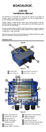
GENERAL VIEW
CBX100
Figure A
Indicator LEDs
1
Cover Screws (2)
2
Compression Connectors (4)
3
25-pin Device Connector
4
Figure B
Power switch (ON/OFF)
1
2 Auxiliary Port Connector
3 Mounting Holes (2)
5
4 ID-NET™Termination
Resistance Switch
Indicator LEDs
6 Backup Module Connector
Spring Clamp Terminal Blocks
7
RS485 Termination
Resistance Switch
8
Power Source Selector
9
Shield to Protection Earth Selector
10
Chassis Grounding Selector
11
SAFETY PRECAUTIONS
ATTENTION: READ THIS INFORMATION BEFORE INSTALLING THE PRODUCT
POWER SUPPLY
This product is intended to be installed by Qualified Personnel only.
This device is intended to be supplied by a UL Listed NEC Class 2 power
source.
CAUTION
Total power consumption is given by adding the
CBX100 power consumption to that of all the devices
powered through the CBX100 (reading device, P.S.,
I/O). Refer to the manual of the connected devices for
details about minimum/maximum supply voltage and
power consumption.
Each CBX100 supports only 1 single reading system
accessories.
SUPPORTED READING DEVICE MODELS
The CBX100 can be directly connected to the following readers through the
25-pin connector illustrated in Figure A.
Linear Scanners
2D Readers
DS2100N DS2400N DS4800 DS6300 MATRIX-1000 MATRIX-2000
DS6400 DX6400 DS8100A
DX8200A
MATRIX
400
NOTE
CBX100 is backward compatible with DS4600A,
DS2100N/DS2400N (black body), and DS1100/DS2200
10-30 Vdc model reading devices using the ADP-MM1
25-pin gender changer. See the Gender Changer
documentation for the relative CBX100 pinout.
OPENING THE CBX100
To install the CBX100 or during normal maintenance, it is necessary to
open it by unscrewing the two cover screws:
CAUTION
The CBX100 must be disconnected from the power
supply during this operation.
MECHANICAL INSTALLATION
CBX100 can be mounted to various wooden or plastic surfaces using the two
self-threading screws (3.9 x 45 mm) and washers provided in the package.
Mounting to other surfaces such as concrete walls or metallic panels
requires user-supplied parts (screws, screw anchors, nuts, etc). A mounting
template is included in the package to facilitate hole drilling alignment.
CBX100 can also be mounted to a DIN rail or a Bosch Frame using the
following mounting accessories: BA100 (93ACC1821), BA200 (93ACC1822).
The diagram below gives the overall dimensions of the CBX100 and shows
the two mounting through-holes.
113
.5
[
4.4
7]
43.3
[1.71]
41.4
[1.63]
4
[0.16]
4
[0.16
]
62
[2.4]
138
[5.4]
128
[5.0]
30.
8
[1.21
]
Figure 1 - Overall Dimensions
ELECTRICAL CONNECTIONS AND SETUP
The following figure shows a typical layout.
Figure 2 – System Layout
The dotted line in the figure refers to an optional (temporary) hardware
configuration in which a portable PC can be quickly connected to the
CBX100 (and consequently to the reading device auxiliary interface)
through the internal 9-pin connector. This allows monitoring of the data
transmitted by the reading device or configuration through the utility
program (see the reading device Installation Manual for more details). The
reading device auxiliary interface signals are also available on the internal
spring clamp connectors.
After making system cabling and switch settings, connect the reading
device to the 25-pin connector on the CBX100 housing.
Switch ON the CBX100 power switch (see Figure 3). The Power LED turns
on (blue) when the power connection has the correct polarity. The Power
LED turns on (red) in case of wrong polarity.
After system functioning has been verified, close the CBX100 using the 2
cover screws.
POWER SUPPLY
Power is supplied to the CBX100 through the Vdc and GND pins provided
on the spring clamp connector.
The power switch (see Figure 3) switches the power supply ON or OFF for
both the CBX100 and the connected reading device.
CAUTION
The power switch does not control power to the
Vdc/GND, +V/-V spring clamps, therefore any devices
connected to these signals (i.e. external trigger,
encoder, etc.), are live and are not protected from
polarity inversion. Disconnect the power supply when
working inside the CBX100.
OFF
ON
CBX100
POWER SUPPLY
GND
GND
Vdc
V+ (10 - 30 Vdc)
Earth
Earth Ground
Figure 3 - Power Switch ON/OFF Positions and Connections
NOTE
Vdc is electrically connected to +V, just as GND is
electrically connected to -V. This is useful for supplying
external trigger, inputs and outputs from the CBX100
power source, hV and -V signals should not be
used as power supply inputs to the CBX100.
The power supply must be between 10 and 30 Vdc only.
NOTE
To avoid electromagnetic interference:
-
Connect CBX100 Protection Earth (Earth) to a good
earth ground.
-
Connect the reading device chassis to earth ground
through the jumper, (default setting, see Figure 7).
-
Connect the Network Cable Shield (Shield) to Filtered
Earth through the jumper (default setting, see Figure 6).
SYSTEM WIRING
The connection and wiring procedure for CBX100 is described as follows:
1) Open the CBX100 by unscrewing the 2 cover screws.
2) Verify that the CBX100 power switch is off (see Figure 3).
3) Unscrew the compression connectors and pass all the system cables
through them into the CBX100 housing.
4) To connect the power and input/output signals:
•
Prepare the individual wires of the system cables by stripping the
insulation back approximately 1 cm.
•
Using a device such as a screwdriver, push down on the lever
directly next to the clamp (see Figure 4).
•
Insert the wire into the clamp and release the lever.
The wire will now be held in the spring clamp.
5) Tighten the compression connector nuts so that the internal glands seal
around the cables.
Figure 4 - System Cable Connections
Flexible stranded wire should be used and must meet the following
specifications.
All positions:
24 - 16 AWG
0.2 - 1.5 mm²
The CBX100 spring clamp connector pinouts are indicated in the Pinout
table.
Refer to the reading device Installation Manual for signal details.
Pinouts
Group Name Function
Vdc
Power Supply Input V
GND
Power Supply Input Voltage -
Input
Power
Earth
Protection Earth Ground
+V
Power Source – External Trigger
I1A
External Trigger A (polarity insensitive)
I1B
External Trigger B (polarity insensitive)
External
Trigger
Input
-V
Power Reference – External Trigger
+V
Power Source – Inputs
I2A
Input 2 A (polarity insensitive)
I2B
Input 2 B (polarity insensitive)
Generic
Input
-V
Power Reference – Inputs
+V
Power Source – Outputs
-V
Power Reference – Outputs
O1+
Output 1 +
O1-
Output 1 -
O2+
Output 2 +
Outputs
O2-
Output 2 -
TX
Auxiliary Interface TX
RX
Auxiliary Interface RX
Auxiliary
Interface
SGND
Auxiliary Interface Reference
REF Network
Reference
ID+
ID-NET™ N
ID-NET™
ID-
ID-NET™ Network -
Network
Shield
Network Cable Shield
RS232 RS485FD
RS485HD
TX
TX+
RTX+
RTS
TX-
RTX-
RX
*RX+
CTS
*RX-
Main
Interface
SGND
SGND
SGND
The input power signals
Vdc
,
GND
and
Earth
as well as the network signals
REF
,
ID+
,
ID-
and
Shield
are repeated to facilitate system cabling. In this way the power and
network busses can enter and exit the CBX100 from different spring clamps but be
physically connected together.
Reading Device
Configuration PC
PWR
Scanner
CBX100
Scanner
Auxiliary
Interface
PS, I/O, Main Interface
1
2
3
4
5
6
7
8
9
10
11
Mounting
Holes
4
3
2
1


