background image

C-BOX 300/310

Installation Manual

Содержание C-BOX 300

Страница 1: ...C BOX 300 310 Installation Manual...

Страница 2: ...C BOX 300 310 Installation Manual...

Страница 3: ...C BOX 300 310 INSTALLATION MANUAL...

Страница 4: ...ments without prior notification Datalogic shall not be liable for technical or editorial errors or omissions contained herein nor for incidental or consequential damages resulting from the use of thi...

Страница 5: ...p 7 2 5 1 Power Supply 8 2 5 2 System Wiring 10 2 5 3 Chassis Grounding Jumper Settings 12 2 5 4 Profibus Node Address Selection 12 2 5 5 Connection to a Profibus Network 13 C BOX 3X0 Configuration fo...

Страница 6: ...e section Safety Precautions at the beginning of this manual 2 Correctly position and mount the C BOX 3X0 within the reach of the barcode scanner cable according to the information in paragraph 2 4 3...

Страница 7: ...v GENERAL VIEW C BOX 300 1 2 3 4 Figure A 25 pin scanner connector Cover screws 4 Compression connectors 1 2 3 Profibus connector 4...

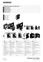
Страница 8: ...vi C BOX 310 1 2 Figure B LCD display Keypad 1 2...

Страница 9: ...C BOX 300 310 8 5 1 4 6 2 3 7 Figure C Cover inside Configuration switch 1 2 LCD contrast trimmer 3 Power on LED 4 Tx LED 5 Diagnostic LED 1 6 7 8 Diagnostic LED 2 Diagnostic LED 3 Node address select...

Страница 10: ...5 6 2 1 3 9 7 8 Figure E Bottom inside Power on switch 1 2 Chassis grounding selector 3 Spring clamp terminal blocks 5 4 GET button TEST button 6 SEND button 7 8 9 Auxiliary port connector OM4000 jum...

Страница 11: ...ix C BOX 310 Figure D Bottom inside...

Страница 12: ...and damage to equipment and to ensure that the C BOX 3X0 functions correctly Safety regulations Observe the guidelines in the VDE 0100 regulations for handling electrical components Observe the applic...

Страница 13: ...ts are led to ground through the shielding rail which is electrically connected to the case To ensure that the interference currents which flow through the shielding do not themselves interfere with o...

Страница 14: ...xii...

Страница 15: ...Send the configuration stored in memory to the scanner In the C BOX 310 visualize the data packet sent by the scanner on the LCD The C BOX 300 C BOX 310 mechanical dimensions are 167 x 115 x 61 mm 6 5...

Страница 16: ...and all the parts supplied with the equipment are present and intact when opening the packaging the list of parts includes 1 C BOX 3X0 2 Installation manual 3 C BOX 3X0 configuration program disk 4 2...

Страница 17: ...crews CAUTION The C BOX 3X0 must be disconnected from the power supply during this operation C BOX 300 C BOX 310 Figure 2 Opening the C BOX 3X0 It is possible to perform the following operations Proce...

Страница 18: ...3X0 back side The purpose of this label is to keep the C BOX 3X0 cover and bottom part together when the scanner is open Figure 3 Adhesive label To apply the label refer to the figures below When app...

Страница 19: ...ANICAL INSTALLATION The diagram below gives the overall dimensions of the C BOX 3X0 and may be used for its installation 3 5 0 14 mm inch 167 6 57 150 5 91 66 2 60 95 3 75 115 4 53 60 2 36 90 3 54 Fig...

Страница 20: ...gure 6 To mount the C BOX 3X0 1 Open the C BOX 3X0 by unscrewing the 4 cover screws If necessary using the two mounting holes inside the device as a pattern mark the panel with an appropriate object a...

Страница 21: ...g clamp connectors After making system cabling and switch settings see sub paragraphs under 2 5 connect the scanner to the 25 pin connector on the left side of the C BOX 3X0 housing Switch ON the C BO...

Страница 22: ...both the C BOX 3X0 and the connected scanner ON OFF S1 Figure 8 Power switch ON OFF positions C BOX 1 2 VS GND USER INTERFACE GND V 10 30 Vdc Figure 9 Power supply connections The power supply must b...

Страница 23: ...ge equipment Make sure that the C BOX is correctly grounded WARNING Although the C BOX 3X0 is protected against polarity reversal connecting up the power feed with incorrect polarity for extended peri...

Страница 24: ...OX 3X0 housing 4 To connect the power and input output signals Prepare the individual wires of the system cables by stripping the insulation back approximately 1 cm Using a device such as a screwdrive...

Страница 25: ...2 4 6 GND 7 8 EARTH GROUND 9 12 20 33 34 40 Reserved 21 OUT1 23 OUT2 27 EXT TRIG 28 EXT TRIG 35 TXA 37 RXA 39 SGND DS2100 DS2400 DS4300 DS4600 22 OUT REF OUT1 24 OUT REF OUT2 25 26 NC Reserved 29 NC...

Страница 26: ...default to GND floating Figure 11 Chassis grounding The C BOX 3X0 is now installed which completes the electrical connections for your scanning system 2 5 4 Profibus Node Address Selection To interfa...

Страница 27: ...nnectors for connecting to the bus Use connectors from ERNI and Siemens If the C BOX is installed at the beginning or end of the PROFIBUS cable segment it is recommended to use PROFIBUS connectors whi...

Страница 28: ...cation as described in the configurator s Help On Line or User s Manual NOTE Further information on PROFIBUS protocol and Flow control is provided in the C BOX 300 310 PROFIBUS document and Help On Li...

Страница 29: ...ion the C BOX 3X0 is in the normal operating mode It communicates with the scanner through the 9 pin internal connector and the scanner auxiliary serial interface The internal connector pinout is illu...

Страница 30: ...t see WinHost Help On Line The C BOX 310 display visualizes an appropriate message Once the C BOX 3X0 configuration is completed it is necessary to replace the switch in the Normal Operation position...

Страница 31: ...12 2 8 OPERATING MODES With the C BOX 3X0 three operating modes are possible Normal Operation Once the connection procedure is completed the warning LED is OFF the C BOX 3X0 is ready to receive code s...

Страница 32: ...second the warning LED is turned ON 2 Release the buttons 3 Press the left button corresponding to the GET function the center button corresponding to the TEST function or the right button correspond...

Страница 33: ...s own permanent memory support to the scanner s EEPROM NOTE Once the buttons are released in step 1 a ten second timeout starts If no button is pressed within this time no function is selected the pro...

Страница 34: ...C BOX 300 310 20 2 2 8 2 LED Indicators Power on LD3 TX LD1 LD2 Warning LED Figure 17 LED Indicators In the C BOX 300 the Warning LED is repeated in the bottom inside Warning LED Figure 18 C BOX 300...

Страница 35: ...uring a GET TEST SEND procedure or during the Configuration Mode It blinks when an error condition occurs Normally this LED should be OFF TX LD3 green indicate the Profibus Network activity When commu...

Страница 36: ...pin male connector see DIN 19245 part 1 and plug it into the 9 pin female external connector 5 1 9 6 9 pin external female connector pinout Pin Name Function 1 N C not connected 2 N C not connected 3...

Страница 37: ...mory PROFIBUS INTERFACE Interface type Data transfer rate RS485 bit s 9600 19200 93750 187500 0 5M 1 5M 3M 6M 12M automatic detection of the data transfer rate ENVIRONMENTAL FEATURES Operating tempera...

Страница 38: ...of Member States relating to electromagnetic compatibility and product safety Bas e sur la l gislation des Etates membres relative la compatibilit lectromagn tique et la s curit des produits ber die...

Отзывы: