Dalsa SC-34-02K80-00-R, User Manual
The Dalsa SC-34-02K80-00-R User Manual is an essential documentation for effectively operating this product. Easily accessible for free download at manualshive.com, this comprehensive manual provides step-by-step instructions, useful tips, and troubleshooting guidance. Optimize your product usage with this user-friendly manual at your fingertips.
Share
Download


Reviews:
No comments
Related manuals for SC-34-02K80-00-R
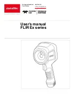
FLIR Ex Series
Brand: DATATEC Pages: 41

K-CAM-USB
Brand: Kramer Pages: 3

ICA-HM101
Brand: Planet Pages: 2

Sony E mount
Brand: Samyang Pages: 11

Bullet White
Brand: Y-cam Pages: 2

CCDVR32
Brand: Mini Gadgets Pages: 5

19CWM
Brand: HP Pages: 57

vs-570s
Brand: Bolt Pages: 48

PCDVRR700X
Brand: Prestigio Pages: 23

E44A
Brand: ACTi Pages: 39

E33
Brand: ACTi Pages: 34

VS-510OP
Brand: Bolt Pages: 44

ACAM07BK
Brand: nedis Pages: 96

CL796P
Brand: Spedal Pages: 15

ENFORCER DX1
Brand: Raytis Pages: 20

R50
Brand: Kaiser Baas Pages: 7

Car camera
Brand: Kaiser Baas Pages: 17

R10
Brand: Kaiser Baas Pages: 20


