


Dakota Micro, Inc.
Rev: 06/26/17 Page 1 of 12
Author: CNR
Users Manual
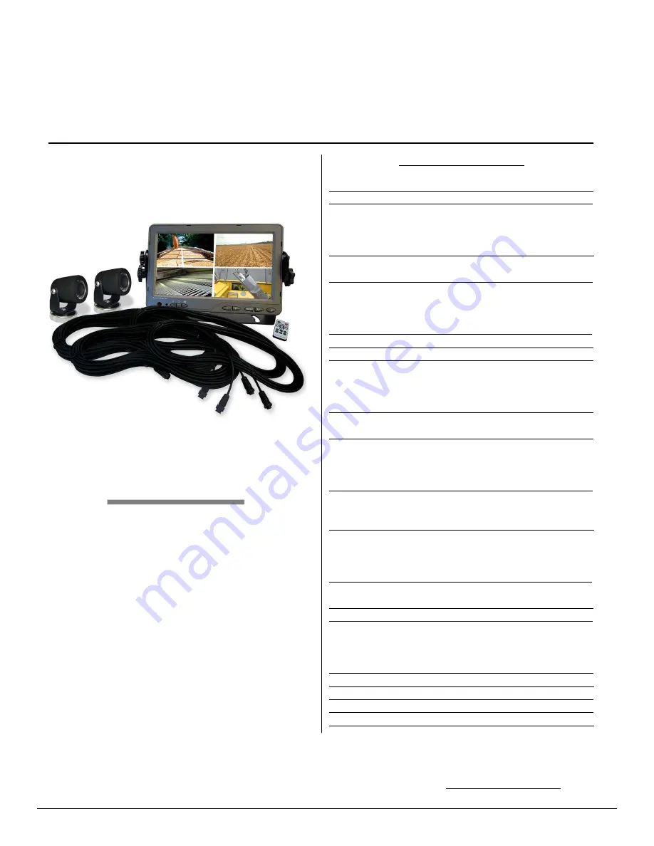
AGCO AgCam®
Part Number: AC‐9MQ (‐C2)
Reliable
Profitable
Capable
Always read the manual prior to operating this equipment. Also, please follow all safety signs and precautions.
See the AGCO Dakota Micro, Inc. website for installation training videos at www.agcocameras.com.
Table of Contents
I. Included Monitor & Camera Kit Components 2
II. Standard Features 2‐3
A. Cameras
B. Monitors
C. Cables
III. Parts of an AgCam 3
A. Camera
IV. Camera Mounting 3‐4
A. Temporary Mounting
B. Permanent Mounting
C. Suggestions for Camera Mounting
V. Camera Warnings 4
VI. Cable Routing Tips & Warnings 4
VII. Monitor Installation & Mounting 4‐5
A. Mounting Precautions
B. Universal Bracket Mounting
C. Finalizing Universal Bracket Installation
VIII. Installation 5
A. Monitor Wire Harness Details
IX. Power 5
A. Supplying Power with 12v Power Adaptor
B. Hardwire Power Adaptor
C. Fuses
X. Event Trigger Wire Operations 6
A. Event Trigger Wire Color Guide
B. Event Trigger Wires Explained
XI. Monitor, Quad, & Remote Operation 6‐7
A. Quad Monitor Operations ‐ Front
B. Quad Monitor Operations ‐ Back
C. Remote Operations
XII. Standard Monitor Menu Settings 8
A. Standard Monitor Menu Settings Navigation
XIII. Quad Menu Settings 9‐10
XIV. Specifications 10
A. Camera
B. LCD Monitor
C. Quad Processor
XV. Warnings 11
XVI. Product Warranty/Repair Process 12
XVII. Consumer Limited Warranty 12
XVIII. Disclaimer 12
XVIV. Contact Us 12
MORE


