background image


ODY-17-1 

DIGITAL COMPASS DISPLAY 

 
Introduction: 

The Odyssey gauge series from Dakota Digital, Inc. incorporates the 

reliability and quality of our standard gauges, along with several unique features 
and easy mounting.  These features include:   

 Microprocessor 

accuracy. 

  Night dimming feature. 

  Digital heading readout along with standard letter heading abbreviation. 

  Can be calibrated to compensate for vehicle’s magnetic interference. 

  Can be calibrated to compensate for difference between magnetic north and 

true, or map, north. 

  Does not require constant power to maintain calibration settings. 

  High Visibility full character VFD display. 

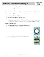
The Odyssey series digital compass display will show the current heading 

direction your vehicle is traveling in.  The vehicle calibration procedure ensures 
accurate information will be presented. 

All compasses, whether electronic or mechanical, determine the current 

heading from the earth’s magnetic field.  Automobiles have many electric 
accessories and high current devices, such as the alternator, ignition system, 
headlights, etc.  Each of these also creates a small magnetic field.  Since all of 
these magnetic fields add together, a standard compass can be fooled into 
showing a false reading.  Because the major sources of interference in the 
vehicle are fairly constant, the Dakota Digital compass has a calibration 
procedure that filters these out. 


The earth’s magnetic field also does not match up exactly with true north, 

also referred to as map north.  The magnetic field is tilted.  Due to this the 
difference between two is not same in different parts of the globe.  The Dakota 
Digital compass has a calibration procedure that allows you to add an offset to 
the reading to compensate for the deviation. 

In spite of the many advanced features of there are some things that can 

still fool the compass and cause small deviations.  A high current device being 
switches on or off (like the headlights or air conditioner) can cause deviations of 

±

5 to 

±

10 degrees.  A large truck passing by you can cause up to 

±

5 degrees 

variation.  Travelling over or under a bridge or other large steel structure can 
cause 

±

5 to 

±

10 degree variations.  Driving in a hilly region can cause 

±

5 to 

±

10 

degree variations due to the tilt of the vehicle and the sensor. 


Summary of Contents for Odyssey ODY-17-1

Page 1: ...nition system headlights etc Each of these also creates a small magnetic field Since all of these magnetic fields add together a standard compass can be fooled into showing a false reading Because the major sources of interference in the vehicle are fairly constant the Dakota Digital compass has a calibration procedure that filters these out The earth s magnetic field also does not match up exactl...

Page 2: ...sate for the difference between true north and magnetic north This feature can also be used to compensate for misalignment of the compass with the front of the vehicle The compensation range is from 30 to 30 in 2 degree increments The calibration number is stored in a non volatile memory component that does not require power to keep its memory 1 Make sure the ignition key is off so the compass is ...

Page 3: ...d on the front of the bezel while you start the engine 3 After the display lights up release the button The display will show a number 4 Press and release the button until CAL is displayed 5 Press and hold the button The display will show CALIBRAT 6 Release the button Once the compass has taken its initial reading it will display TURN 180 7 Move the vehicle so that it is facing the exact opposite ...

Page 4: ...The interference from a wire drops off very rapidly with distance When the wire is 2x farther away the interference drops if the wire is 3x farther away the interference drops 1 9 Steel rods or bars affect the sensor by bending the magnetic field The magnetic field will have a tendency to follow the steel Due to these limitations we do not recommend mounting the sensor under the dash Good mounting...

Page 5: ... 7 8 x 1 11 16 It should be inserted into the opening from the front and the U clamp will be installed from the back Tighten the two nuts on the U clamp so that the gauge is secure Figure 2 shows the required cut out for the gauge Figure 3 shows how the gauge mounts ...

Page 6: ...sor cable for cuts or abrasions broken Sensor is damaged Return sensor for repair see instructions Gauge is damaged Return gauge for repair see instructions Gauge will not dim Blue wire is not connected Check wiring connections correctly Gauge remains dim at all Blue wire is getting power Connect blue wire to location that only times all of the time has power when the headlights are on Battery is ...

Page 7: ...r installation mishandling misuse neglect or accident This Warranty is in lieu of all other express warranties or liabilities ANY IMPLIED WARRANTIES INCLUDING ANY IMPLIED WARRANTY OF MERCHANTABLITY SHALL BE LIMITED TO THE DURATION OF THIS WRITTEN WARRANTY ANY ACTION FOR BREACH OF ANY WARRANTY HEREUNDER INCLUDING ANY IMPLIED WARRANTY OF MERCHANTABLITY MUST BE BROUGHT WITHIN A PERIOD OF 24 MONTHS FR...

Reviews: