


Reviews:
No comments
Related manuals for SERHQ032BAW1

BA-4 AIR-JECT
Brand: bannerman Pages: 16

HRW D Series
Brand: SMC Networks Pages: 9

MULE 961 QG
Brand: Garland Pages: 184

York YKEP Series
Brand: Johnson Controls Pages: 128
T300 RS
Brand: Husqvarna Pages: 40
T 500RH
Brand: Husqvarna Pages: 20
T 25 RS
Brand: Husqvarna Pages: 21

AR19
Brand: Husqvarna Pages: 56

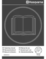
TF324
Brand: Husqvarna Pages: 36

TF 544
Brand: Husqvarna Pages: 28
968981104
Brand: Husqvarna Pages: 14

TF 434 P
Brand: Husqvarna Pages: 48
TF 334
Brand: Husqvarna Pages: 44

TF545D
Brand: Husqvarna Pages: 38
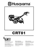
CRT81
Brand: Husqvarna Pages: 64
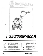
T 350
Brand: Husqvarna Pages: 41

TB1000
Brand: Husqvarna Pages: 44
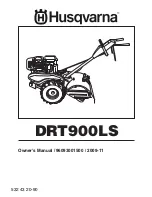
DRT900LS
Brand: Husqvarna Pages: 28


