


Reviews:
No comments
Related manuals for intelligent Touch Manager DCM601B71

Modero G4
Brand: AMX Pages: 140

50901
Brand: Sunforce Pages: 2

NSX-24GT1 (PDF)
Brand: Sony Pages: 2

LCD TV XBR-52LX900
Brand: Sony Pages: 2

KV-36HS420 - 36" Fd Trinitron Wega
Brand: Sony Pages: 1

KE-P42MRX1
Brand: Sony Pages: 2
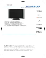
KE-42XS910 - 42" Flat Panel Color Tv
Brand: Sony Pages: 2

KE-42XBR900 - 42" Xbr Plasma Wega™ Integrated Television
Brand: Sony Pages: 2

KE-42TS2 - 42" Flat Panel Color Tv
Brand: Sony Pages: 1

NSX-24GT1 (PDF)
Brand: Sony Pages: 40

KZ-32TS1U
Brand: Sony Pages: 73

KE-MR50M1 CH
Brand: Sony Pages: 68

NSX-24GT1 (PDF)
Brand: Sony Pages: 103
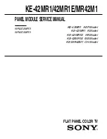
KE-42MR1E
Brand: Sony Pages: 68
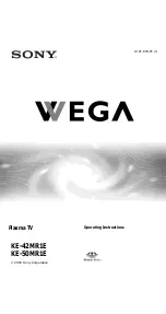
KE-42MR1E
Brand: Sony Pages: 72

KZ-32TS1U
Brand: Sony Pages: 108

KE-50XS910 - 50" Flat Panel Color Tv
Brand: Sony Pages: 101
KE-42XS910 - 42" Flat Panel Color Tv
Brand: Sony Pages: 100


