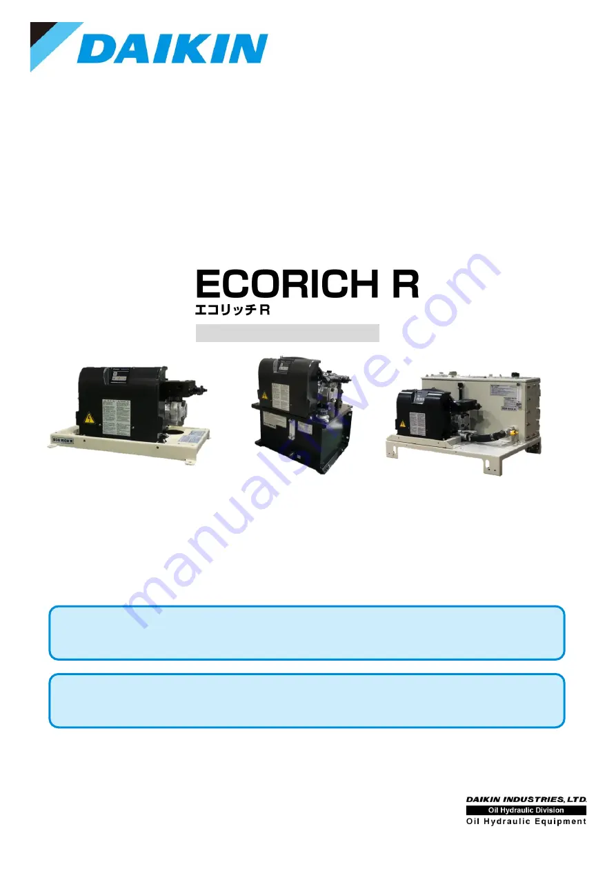
background image


PIM00587 


取扱説明書


Instruction Manual 


H y b r i d   H y d r a u l i c   S y s t e m  


Design #40 Series


EHU15R0700-40-03 / EHU15R0702-40 / EHU15R0703-40-03


EHU15R1000-40-03 / EHU15R1002-40 / EHU15R1003-40-03


EHU30R0700-40-03 / EHU30R0702-40 / EHU30R0703-40-03


日本語

 ................................................ JP-1

JP-97 

English ........................................ EN-1 to EN-102 

Summary of Contents for ECORICH R 40 Series

Page 1: ...b r i d H y d r a u l i c S y s t e m Design 40 Series EHU15R0700 40 03 EHU15R0702 40 EHU15R0703 40 03 EHU15R1000 40 03 EHU15R1002 40 EHU15R1003 40 03 EHU30R0700 40 03 EHU30R0702 40 EHU30R0703 40 03 J...

Page 2: ...CHAPTER 4 PROCEDURE FOR STARTING UP EN 23 CHAPTER 5 CHECKS UPON RECEIVING THE PRODUCT EN 24 5 1 Check on the Contents of the Packaging EN 24 5 2 Check on the Model EN 24 CHAPTER 6 TRANSPORTATION INSTA...

Page 3: ...ion of Run Stop of the Motor Pump EN 69 11 5 Function of the Output of the Alarm Status and Warning Status EN 70 11 5 1 Contact output EN 70 11 5 2 Digital output EN 71 11 5 3 Contact output and digit...

Page 4: ...12 9 2 Cleaning EN 93 12 10 Suction Strainer Maintenance Instructions EN 94 12 10 1 Removal method EN 94 12 10 2 Cleaning EN 95 12 10 3 Reassembly EN 95 12 11 Safety Valve Adjustment Instructions EN...

Page 5: ...without regard to this indication will cause a potentially hazardous condition that may result in moderate or slight injury or property damage NOTICE Improper handling without regard to this indicatio...

Page 6: ...N shall not be responsible for any damage attributable to fire earthquake a third party s action or other accidents or customers intentional acts misuse or use under abnormal conditions DAIKIN shall n...

Page 7: ...es partly completed machinery in the sense of the EC Machinery Directive 2006 42 EC and respectively not usable This product is exclusively intended for integration into a machine or system or for ass...

Page 8: ...ove Refer to the specification documents External dimension sheet for other specifications This manual is subject to change in order to improve the usability of the user s manual and to change the spe...

Page 9: ...risk of electric shock and breakage To move this product use the eye bolts Hoisting it by the pump piping for example will pose a danger of the product falling or overturning Do not install or run thi...

Page 10: ...ine Otherwise there is a risk of injury and failures of the machine Before running the product ensure that you will be able to effect an emergency stop at any time Otherwise there is a risk of injury...

Page 11: ...is a risk of electric shock accidents and damage Do not disassemble this product Otherwise there is a risk of electric shock and injury CAUTION Wear protective glasses and gloves for this work Do not...

Page 12: ...e 1 6 5 Warning plates WARNING The warning plates are very important so do not damage or remove them If a warning plate becomes difficult to read through peeling or losses contact Daikin immediately T...

Page 13: ...5 15 2 3 5 28 5 Coating color Black Purchased parts etc standard color of the equipment manufacturer Digital input 5 channels Photo coupler insulation DC 24 V max 27 V 5 mA positive or negative common...

Page 14: ...combination of those tabled below or codes 11 to 99 when combined Unit options Tank capacity code Description Tank capacity code Description 00 02 03 00 02 03 Code Code 22 Controller cover 07 54 Leve...

Page 15: ...secure with bolts etc Other Be sure to install no fuse breakers at all poles 3 poles or 2 poles at the main circuit power supply side primary side Wire electrical connections so as to satisfy JIS B 9...

Page 16: ...nuous discharge flow rate at the maximum operating pressure according to the model EHU15R 3 L min or less EHU30R 5 L min or less EHU15R0700 40 03 EHU15R0703 40 03 EHU15R1000 40 03 EHU15R1003 40 03 EHU...

Page 17: ...PIM00587 EN 16 2 4 External Dimensions Motor pump type EHU15 30R 00 03 M8 bolts recommend...

Page 18: ...PIM00587 EN 17 20L tank unit type EHU15 30R 02 4 13 holes positions 4 10 holes positions Oil filling drain port Section at A A Dimensions of mounting holes for installation...

Page 19: ...3 Both front and back sides M12 bolts recommended Separately arranged items Cap nut is welded to back side Dimension when attached the installation plate Dimension when attached the installation plate...

Page 20: ...e EHU15 30R 02 Part No Name 1 1 Inverter driven motor pump 1 2 Control unit 2 DC fan 3 Base Part No Name 1 Oil tank 18L 2 Suction strainer 3 Oil level gauge 4 1 Inverter driven motor pump 4 2 Control...

Page 21: ...type EHU15 30R 03 03 Part No Name 1 Oil tank 33L 2 Suction strainer 3 Stop valve 4 Oil level gauge 5 Oil filler port cum air breather 6 1 Inverter driven motor pump 6 1 Control unit 7 Oil cooler Abov...

Page 22: ...t type EHU15 30R 02 Operation panel Control unit DC fan Front View of Unit Valve block Inverter driven motor pump Operation panel Control unit Oil cooler DC fan Oil tank Front View of Unit Valve block...

Page 23: ...e EHU15 30R 03 03 Operation panel Control unit Oil cooler DC fan Front View of Unit Inverter driven motor pump Oil filler port cum air breather Oil level gauge Stop valve Oil tank Top View of Unit Val...

Page 24: ...to check the following points before turning the power on Is the product installed correctly Has the piping been done correctly Has hydraulic oil been supplied Has the wiring been done correctly Is t...

Page 25: ...items are present Hydraulic unit body 1 piece Instruction Manual 1 copy 5 2 Check on the Model Check with the product nameplates that the actual item matches the ordered product The nameplate positio...

Page 26: ...equipment appropriate for the packaged state Otherwise there is a danger of falling or toppling over This is a heavy item and should therefore not be lifted by one person alone Check the product s wei...

Page 27: ...ulic unit in the table above and ensure that the hoisting load is within the rated load of the hoisting equipment NOTICE Do not move the product while there is oil in the tank this could cause malfunc...

Page 28: ...icient maintenance space so that working postures will not be uncomfortable NOTICE If the intake air exhaust spaces described above are not secured the motor and controller will reach high temperature...

Page 29: ...od and position refer to the Delivery Specification outline drawing Motor pump type EHU15 30R 00 03 20L tank unit type EHU15 30R 02 Installation Mounting Hole Dimensions 490 314 4 10 M8 bolts recommen...

Page 30: ...a hazard Be sure to secure it with bolts etc NOTICE Installing the product on a sloping surface may cause oil leakage and inclusion of air in the oil leading to abnormal noises and shortening of equi...

Page 31: ...s not equipped with an oil cooler Use the cooling equipment separately so that they can be used at an appropriate oil temperature Piping Specifications Piping Port Piping Size Recommended Hose Withsta...

Page 32: ...bottom 10cm or more Ensure the distance between the suction port and the return port Or put a baffle plate partition plate Install a filter 40 m or less to the air breather Design the oil tank and mak...

Page 33: ...with sealing tape Piping Specifications Piping Port Piping Size Recommended Hose Withstand Pressure At Shipment P Rc 3 8 EHU R07 10 5 MPa EHU R10 14 0 MPa Vinyl cap DR Rp 3 4 1 5 MPa T1 Rc 1 1 5 MPa...

Page 34: ...he weight of the hose support the hose 7 2 Filling with Hydraulic Oil Tank Unit Type only Remove the cap of the filler port cum air breather by turning it counterclockwise then pour clean hydraulic oi...

Page 35: ...the tank may decrease Add oil to bring the height of the oil level to within the stipulated range Depending on the volumetric capacity of the hydraulic circuits at the machine side the fluctuations in...

Page 36: ...wer supply and input output signal cables pass the cables through the specified cable ports Fit a no fuse breaker conforming to European standard EN60947 2 to the source power supply of the hydraulic...

Page 37: ...hock For the capacity for each model see 8 3 Installation of the Breaker Be sure to ground ground terminals in accordance with the law in the country concerned Make a direct connection without going t...

Page 38: ...or cover needs to be mounted Mount it by following the procedure below 1 Engage the corners of the controller and corners of the cover together 2 Close the cover 3 Holding the grips at the left and ri...

Page 39: ...rior cover go into the mating parts on the interior cover Check that the 7 segment display is located in the center of the display window in the operating section 5 Tighten the two screws in the lower...

Page 40: ...is selected Power ON Normal status Only when communications option selected Communication port for maintenance Hybrid Win connection port Digital output or Ready to run Positive common Negative common...

Page 41: ...6 OHM ELECTRIC Applicable cable outer diameter 13 to 16 2 Use a ground cable the same size as the power cable or larger 3 Connect the cables through the controller s cable port At the wiring port use...

Page 42: ...1 Prepare a cable and cable clamp Recommended Items Cable Size Recommended Cable Recommended Cable Clamp 0 3 0 5 mm2 AWG22 20 KVC 36SB 0 3 0 5 mm2 Kuramo Electric OA W1611 OHM ELECTRIC Applicable cabl...

Page 43: ...N2 Digital input 2 DIN3 Digital input 3 DIN4 Digital input 4 DIN5 Digital input 5 ICOM Digital input common Analog communications 2 Signal cable port 21 hole RS422 485 communications 1 Control communi...

Page 44: ...tion Terminal Block 1 Push on the spring with e g a screwdriver Pushing in the screwdriver will open up the opening for insertion 2 Check the stripped length of the wire and insert it fully home witho...

Page 45: ...sure to terminate shielded cables and connect them to the control communications cable grounding terminal If noise is not eliminated even when connected to the shielded cable grounding terminal make...

Page 46: ...stop command has been input via digital input 1 STP is displayed on the panel Set the time between unit stop and unit at 0 5 seconds or more P Q selection No 0 1 2 3 4 5 6 7 8 9 10 11 12 13 14 15 Dig...

Page 47: ...e command flow rate command has reached the goal DO2 Digital output 2 No output OCOM Digital output common Can be either positive or negative CAUTION Prepare a DC24 V 10 0 5 A power supply externally...

Page 48: ...ositive or negative CAUTION The switching capacity of the contact outputs is DC30 V 0 5 A at resistance load Note that driving a load exceeding the permissible current may damage the contacts or other...

Page 49: ...s operation panel display rises after the sound of the pump running 2 Flushing operation When the starting check is completed connect all the piping except for the actuators in a loop then flush for...

Page 50: ...ey ENT key Used to confirm selections for parameter numbers parameter settings etc 10 2 Functions of the Operation Panel 10 2 1 Function overview The operation panel has the following functions Mode D...

Page 51: ...h momentarily Normal In the normal status the current pressure is displayed Stopped Displayed when a stop command is in effect and when the pressure is 0 15 MPa or lower AC failure This is displayed f...

Page 52: ...n09 Reserved for the system Reserved for the system n10 Motor temperature C Displays the motor temperature n11 Radiating fin temperature C Displays the temperature of the radiating fins n12 Main circ...

Page 53: ...rface PCB temperature C Displays the current approximate temperature inside the controller n27 Reserved for the system Displays 99 n28 to n29 Reserved for the system Displays 0 Displayed only for mode...

Page 54: ...key or key During data number selection the display will flash 3 Confirm the data number by pressing the key The value for the selected data number will be displayed 4 Press the or key This returns yo...

Page 55: ...key or key During data number selection the display will flash 3 Confirm the data number by pressing the key The value for the selected data number will be displayed 4 Change the set value by incremen...

Page 56: ...hange the set values by incrementing or decrementing them with the and keys The data code will be displayed approximately 2 seconds after a set value has been changed 6 Press the key The set value wil...

Page 57: ...isplay Parameter Name 1 Pressure setting 2 Flow rate setting 3 Acceleration time setting 4 Deceleration time setting The first digit displays the PQ selection number It is displayed in hexadecimal 0 F...

Page 58: ...istory number selection the display will flash A00 is the latest alarm with older alarm displayed in sequence in this order A01 A02 3 Confirm the alarm history number with the key The corresponding al...

Page 59: ...r at occurrence of the alarm 5 A u Main circuit DC voltage V DC voltage of the main circuit at occurrence of the alarm 6 A c Radiating fin temperature C Radiating fin temperature at occurrence of the...

Page 60: ...actuation warning has occurred the L63 indication displayed on the operation panel can be retained It is also possible to record the L63 Pressure switch actuation warning in the alarm history althoug...

Page 61: ...Warning 2 ON Normal OFF Alarm or Warning 1 0 No output Alarm or Pressure switch 1 Alarm or Pressure switch or warning P08 Working pressure of P01 Pressure switch Unit 0 or 1 Fixed value MPa 2 The rat...

Page 62: ...1 Setting the change time when the pressure command or flow rate command is decreased at the time of switching the PQ pattern Pressure command Decrease 1MPa time Flow rate command Decrease 1000min 1 t...

Page 63: ...arged and warning 10 Warning output P40 Unused setting items It does not affect the operation but please do not change the setting P41 PCMW Pressure coincidence detection range 0 to 99 5 Setting the p...

Page 64: ...please do not change the setting P58 LVOL Load volume setting 0 to 18 3 This is the control gain for adjusting the response of PQ control The pressure response can be adjusted in accordance with the...

Page 65: ...he factory default If it has been changed to indication in PSI units implement some measure to make it apparent that it is in PSI units such as affixing an indication sticker Prepare this sticker your...

Page 66: ...Flow rate setting L min Ut Acceleration time setting sec MPa dt Deceleration time setting sec 1000min 1 The PQ selection number hexadecimal is displayed in the Pressure and flow rate characteristic c...

Page 67: ...ing DIN2 to DIN5 the pressure and flow rate command value can be selected as shown in the following table Select the PQ selection number by digital input signal PQ selection number The parameters of t...

Page 68: ...N Digital input 4 PQ selection 3 4 OFF ON Digital input 5 PQ selection 4 5 OFF ON PQ5 Pressure setting value PQ14 Pressure setting value PQ selection number Pressure 0 Time PQ0 PQ1 PQ0 PQ0 Pressure PQ...

Page 69: ...d by this parameter Adjust it if you want to change pressure or flow rate and avoid the instability in switching solenoid valve Panel Indication Code Name Operation Range Default Value Unit P12 W_TM S...

Page 70: ...et Value State of DIN1 terminal OFF ON 0 STOPS RUNS 1 RUNS STOPS 1 CAUTION Prepare a DC24 V 10 0 5 A power supply externally It is not possible to supply power from this controller to external destina...

Page 71: ...tput the alarm statuses of this unit Connect them as necessary by following the information below Refer to the 11 5 3 Contact output and digital output selection for changing the output contents Termi...

Page 72: ...puts alarm status and warning status OCOM Digital output common Can be either positive or negative 11 5 3 Contact output and digital output selection By changing the setting values of the parameters P...

Page 73: ...Pressure coincidence output It will become ON when the pressure matches 6 Flow rate coincidence output It will become ON when the flow rate matches 7 Fully charged It will become ON if the main circui...

Page 74: ...figure below Pressure Flow rate Pressure command Pressure Pressure coincidence detection range Flow rate command Flow rate Flow rate coincidence detection range Pressure and flow rate coincidence out...

Page 75: ...ut mix 0 to 507 0 0 10PSI P02 Pressure switch output delay time 0 00 to 9 99 0 00 sec Sets the delay time from when the pressure falls below the set value for P01 Pressure switch to confirmation of th...

Page 76: ...ay P08 Alarm output mix The setting unit of P01 Pressure switch can be selected as shown in the following table P08 Working pressure of P01 Pressure switch Unit 0 or 1 Fixed value MPa 2 The ratio of t...

Page 77: ...control B 3 Set the parameter P58 Load Volume Setting to factory default value 3 4 Turn off the power supply of the hydraulic unit once confirm that the display on the panel turns off and turn the po...

Page 78: ...brought into effect by turning the power off and then back on CAUTION It is necessary to turn the power on again after setting P59 PQ control method selection setting change Be sure to set P58 Load vo...

Page 79: ...ess starting time longer it suppresses the occurrence of pressure surge Panel Indication Code Name Operation Range Default Value Unit P32 S_TM Surge less starting time 0 01 to 9 99 0 5 sec P33 L_IN Mo...

Page 80: ...290 72 PSI P36 DR_T Dry operation judgment time 0 01 to 99 9 3 00 sec When the pressure flow rate is in the dry operation detection area shown in the figure below and P36 Dry operation judgement time...

Page 81: ...act A contact B contact Power OFF Power ON Normal Alarm occurs 3 3 L63 Pressure switch operation 2 2 Warning occurs 1 1 It depends on the setting of P07 Warning output level setting Refer to 11 5 3 Co...

Page 82: ...cuit failure Replace controller E08 Regenerative circuit error Regenerative resistence disconnection Replace controller Regenerative switch device failure E10 Output device error Motor control error A...

Page 83: ...error The load torque is larger than usual Replace the motor or motor pump Sudden deceleration operation cycle is short Increase the parameter value of P13 to P28 deceleration time setting Encoder fa...

Page 84: ...performance The motor rotation speed has risen The ambient temperature is too high E46 Board thermistor disconnection short circuit Controller interior Interface board failure Replace controller inte...

Page 85: ...nd re set the safety valve Refer to the 12 11 Safety Valve Adjustment Instructions Replace the motor or motor pump The ambient temperature is too high Bring the ambient temperature to within the stipu...

Page 86: ...alue set for parameter P01 Pressure switch or lower If there is nothing abnormal in the operation of the main machine review the set value for the pressure switch or the delay time 12 5 Periodic Maint...

Page 87: ...for dust accumulation Accumulated dust will lessen the cooling effect so it should be cleaned Check if the ambient temperature has exceeded 40 C Control unit Once a month Check if the ambient tempera...

Page 88: ...ean See 12 10 Suction Strainer Maintenance Instructions DANGER When touching the interior of the controller abide by the following procedure to prevent electric shocks 1 Shut off the source power supp...

Page 89: ...during the work Note that oil will flow out from the piping and oil cooler during disassembly 12 7 1 Removing the oil cooler 1 Disconnect the connector for the DC fan wiring 2 Remove the hose clamps 2...

Page 90: ...DC fan 3 Remove four cross recessed pan head screw and washer assemblies M4 10L and separate the resin shroud and core Four push rivets Use a small screwdriver etc and pull up as in to Push rivets Enl...

Page 91: ...low wear protective glasses to avoid getting deposits and dirt in your eyes core NOTICE Take care to ensure that dirt or adhering material is not blown into the interior of the core 12 7 4 Cleaning th...

Page 92: ...to confuse the directions of air intake exhaust of the oil cooler The wind blows from the unlabeled side to the labeled side See 6 2 1 Secure the space for air intake exhaust After completion of reass...

Page 93: ...the figure of the filter and pulling it up to the top of the unit 12 8 2 Cleaning Air blow the filter to remove dirt or dirt that may have accumulated adhered to it WARNING When using air blow wear p...

Page 94: ...t off the source power supply Wear protective glasses and gloves for this work 12 9 1 Removal fitting To remove it turn the cap in the counterclockwise direction by hand To fit it turn the cap in the...

Page 95: ...oil drainage port open the oil drain plug M12 20L and drain out all of the hydraulic oil in the tank 2 Remove the four hexagonal bolts M8 20L securing the top plate and tank and hoist the strainer by...

Page 96: ...and remove it Hexagon nut Width across flats 41 mm 12 10 2 Cleaning Air blow the suction strainer to blow off deposits and adhering material Also remove foreign matter inside the cylinder part of the...

Page 97: ...tructions 1 Referring to the enlarged view of the safety valve on the next page loosen the lock nut Lock nut M10 width across flats of 14 mm 2 In accordance with the guidance diagram for the length of...

Page 98: ...0 1 5 1 0 15 19 17 16 18 20 21 22 23 24 Pressure adjustment screw length Rough Diagram Lock nut Pressure adjustment screw length mm PC set pressure MPa Detail of Safety Valve Pressure adjustment scre...

Page 99: ...Wrap sealing tape around the hexagon socket head plug Rc 1 8 and fit it as it was Mounting the fixed throttle will also change the rotational speed in the pressure holding status so adjust to the app...

Page 100: ...speed 3 Loosen the lock nut of the throttle valve for minimum rotational speed adjustment 4 Adjust the throttle valve while monitoring the actual motor rotation speed displayed The motor rotation spee...

Page 101: ...ix is 1 OFF ON OFF ON Power supply 3 phase Digital input Digital output OFF Approx 0 02s Unit operation Display OFF ON OFF ON OFF Approx 0 2s DIN0 start stop signal DO2 Command possible Command imposs...

Page 102: ...tart by start stop signal Pressure control state Charge Magnetic pole detection Start by start stop signal Flow control state PQ selection 0 Power supply 3 phase Digital input DO1or2 Output selection...

Page 103: ...ving set values makes control easier 3 Reading and saving the alarm history This is useful for speeding up the identification of parts that need maintenance and shortening stoppage times It serves as...

Page 104: ...lic For requirements on Maintenance Repair Operation All World Machinery Supply Inc United States Daikin Group Company 6164 All World Way Roscoe IL 61073 U S A Phone 1 815 943 9111 Home Page http www...

Reviews: