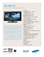
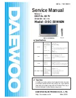
background image

Service Manual

Model : DSC-30W60N

http : //svc.dwe.co.kr

Mar. 2000

DAEWOO ELECTRONICS CO., LTD.

S/M No. :  TSC110NEF0

CHASSIS : SC-110

DIGITAL HDTV

Relese 1

DSC-30W60N

R-V3

General

Power Requirement 

AC 120V, 60Hz

Power Consumption

250W (1.7W in standby)

Dimensions(W/H/D)

890 

x

 573 

x

 560 mm

Weight 

64kg

Antenna

Two 75 ohm external input terminals for UHF/VHF/Cable
One 75ohm external output terminal for Cable

RF Band Coverage 

VHF 2 ~ 13
UHF 14 ~ 69
CATV 1, 14 ~ 125

Picture

Screen Size 

32 inches Pure Flat  16:9 Aspect ratio

Display Format 

1920 

x

 1080i (Digital)

Upconversion to 1080i with line doubling (NTSC)

Horizontal Resolution 

800 Lines

Sound

Digital Audio 

Dolby Digital AC-3 / Pro logic

NTSC Audio

Multi-CH TV Stereo (MTS) / Second Audio Program (SAP)

Audio Power

8W / ch (Main L/R, Woofer), 5W / ch (Center, SL, SR)

Number of Inputs / Outputs

A/V In

4 each (Video / L / R)

S-Video In 

2 each

HD Component Video In 

2 each ( Y/  Pb / Pr, R / G / B )

HD Component Audio In 

1 each ( L / R / SL / SR  / Center / Woofer )

Digital Audio In

2 each ( Coaxial / Optical )

Digital Audio Out

2 each ( Coaxial / Optical )

External Speaker Out 

1 each ( SL / SR / Woofer) 

Specifications

✔ 

Caution

: In this Manual, some parts can be changed for improving, their 

  performance without notice in the parts list. So, if you need the 

  latest parts information,please refer to PPL(Parts Price List) in 

  Service Information Center (http://svc.dwe.co.kr).

Summary of Contents for DSC-30W60N

Page 1: ...th line doubling NTSC Horizontal Resolution 800 Lines Sound Digital Audio Dolby Digital AC 3 Pro logic NTSC Audio Multi CH TV Stereo MTS Second Audio Program SAP Audio Power 8W ch Main L R Woofer 5W c...

Page 2: ...7 8 Troubleshooting Charts 18 9 Parts List 45 10 Circuit Digram 59 10 1 Connection Diagram 59 10 2 Signal Flow Diagram 60 10 3 Power Circuit 61 10 4 Main Circcuit 62 10 5 Video 1 Circuit 63 10 6 Video...

Page 3: ...k hazard and must be corrected imme diately GRAPHIC SYMBOLS The lightning flash with arrowhead symbol within an equilateral triangle is intended to alert the service personnel to the presence of unins...

Page 4: ...4 Wall and shelf mounted installations using a commercial mounting kit must follow the factory approved mounting instructions A receiver mounted to a shelf or platform must retain its original feet o...

Page 5: ...o DisplayFormat 1920x 1080i Digital Upconversion to 1080i with line doubling NTSC HorizontalResolution 800 Lines Sound Digital Audio Dolby Digital AC 3 Pro logic NTSC Audio Multi CH TV Stereo MTS Seco...

Page 6: ...again to make the menus disappear 4 SEL Select button Press to select items on the HDTV menus 5 Arrow buttons PresstonavigatethroughtheHDTVmenus 6 STAT Channel Station button Press to quickly select...

Page 7: ...videotape 18 STOPbutton Press to stop a VCR 19 REW Rewind button Presstorewindavideocassette 20 SCREEN MODE button Press to select how to view your HDTV Normal or Full 21 ADD ERASE button Press to add...

Page 8: ...on or which has been altered in any way that affects the reliability or detracts from its performance How you get warranty service Warrany service can only be provided by an authorized DECA service ce...

Page 9: ...own and a horizontal line appears on the screen 3 S3 Sound Controls mode 4 S4 Video Controls mode 1 MUTE SELECT POWER 1 2 3 9 MUTE S1 Heat Run S2 Screen Voltage S3 Sound Controls S4 Video Controls S5...

Page 10: ...y Setting V Size Max V Size V Position V C Linearity V S Linearity H Size H Position Pincusion Side Pin W Side Pin S Trapezoid Side Pin Balance H Duty Parallelogram H Focus Phase H Focus Amplitude Whi...

Page 11: ...Pressing of CHANNEL s button changes the adjustment items t button for reverse order 4 Adjusting the data 1 With the user remote control Pressing of ARROW button changes the value of data button for r...

Page 12: ...ion will be down and a horizontal line will appear on the screen 2 Turn the variable screen volume of FBT to adjust screen voltage at the point that a horizontal line only just appears Focus Adjustmen...

Page 13: ...individual values with VOLUME Up or Down buttons 4 Repeat two processes above until the white balance is completed Sub Brightness Adjustment 1 Tune on Retma Pattern 2 Press S8 button 3 The following O...

Page 14: ...mode should be selected on Full mode 3 AdjustVerticalSizesothatoverscanningratemaybe105 4 Check if the center circle is not only circular on Full mode but also on Normal mode VerticalSize 1 There is...

Page 15: ...ceive NTSC Retma signal 2 The Screen mode should be selected on Full mode 3 Adjust Vertical Position so that the circle of Retma signal may be centered in the vertical direction Pincushion 1 Receive N...

Page 16: ...lanced shape SidePin Balance 1 Receive NTSC Cross signal 2 The Screen mode should be selected on Full mode 3 When both the left and right screen shape is not symmetrical but on one side adjust Side Pi...

Page 17: ...n the Blanking Board Y Level Adjustment to DTV Decoder module 1 Tune on SMPTE Color Bar signal 2 Connect a scope probe to pin 9 of PW06V 3 Adjust RV900 such as the following figure so that the amplitu...

Page 18: ...izontal deflection system high voltage system or B system the X Radiation Protection Circuit Test must be tested for proper operation as follows 2 1 Operate the HDTV set for at least 15 minutes 2 2 Pe...

Page 19: ...Y output is 0 9Vp p to Yout of PV1 Check if the color burst of C signal is 170 180mV to Cout of PV1 Check QCA4 FA1 and QCA1 Check QCA8 FA2 and QCA5 OSD is on the screen Check video signal of IC210 Vid...

Page 20: ...Y Q204 Q205 Pb Q202 Q203 Pr Q200 Q201 Check if Y Pb and Pr are input to pins 58 59 and 57 of IC200 Check the following parts Y pin 27 of IC200 Q208 Q209 and Q210 Pb pin 15 of IC200 Pr pin 13 of IC200...

Page 21: ...Q217 There are R signal to R504 G signal to R513 and B signal The signal amplitude of cathode G 130Vp p 10Vp p Input signal 10 steps pattern Video mode Normal mode Check the following parts R pin8 of...

Page 22: ...ect the switch to Y Pb Pr Check if Y Pb Pr signals are well connected to input terminals Check if pin 18 of IC212 is Low Check the input output signal of IC207 Pins 9 10 and 11 Low Pin 14 Y signal Pin...

Page 23: ...s 9 10 11 High Pin 13 Y in Pin 1 B Y in Pin 3 R Y in Check IC207 Check the input output signal of IC208 Pins 9 10 11 High Base of QC215 Low Pin 14 Y signal Pin 15 B Y signal Pin 4 R Y signal Check IC2...

Page 24: ...mVp p SIF is to pin 67 of IC215 Check if R L signals are output to IC210 Audio R pin 32 Audio L pin 33 Check if R L signals are input and output to IC215 Audio L input pin 50 Audio L output pin 37 Aud...

Page 25: ...dio output of I609 is equalized signal Audio L input pin 1 Audio R input pin 30 Audio L output pin 12 Audio R output pin 19 Check I609 Check if R L signals are input and output to I607 Audio L input p...

Page 26: ...n 54 HD_R output pin 36 Check the input output signal of volume control IC SL input output pins 6 7 of I606 SR input output pins 4 3 of I606 Center input output pins 6 7 of I605 Woofer input output pi...

Page 27: ...er and Woofer to PA12D R L Woofer Center SR SL To DTV Decoder module NO Decoder R L A1 END Check the following audio signals S_L input output pins 5 6 of I603 S_R input output pins 1 2 of I603 Center...

Page 28: ...n 13 Check the input output signal of IC206 Pins 9 10 and 11 High To be HD Component Low No HD Component HD from pin 15 of IC 206 to PW03M VD from pin 4 of IC 206 to PW03M Check the input output signa...

Page 29: ...is to pin 1 of IC216 Pins 9 10 and 11 High to be HD Component Low no HD Component Check IC209 HP signal is input to pin 1 DEC_HS HP is output to pin 15 EVEN ODD VP signal is input to pin 13 DEC_VS EV...

Page 30: ...ut output to pins 15 2 of IC209 DEC_VS is input output to pins 14 13 of IC209 Pins 10 11 of IC 202 High Base of QC215 High DEC_HS is input to pin 12 of IC 202 DEC_VS is input to pin 2 of IC 202 H_sync...

Page 31: ...T If the LED changes from green to red check pin 39 TXD of IC212 5Vp p Check the pin 38 RXD of IC212 or pin 6 of PA05D 3 3Vp p IC212 communicates with I402 on the IIC bus Check the pins 3 SDA and 4 SC...

Page 32: ...put to pin 2 of I407 2Vp p 6Vp p 33 75KHz Check Q416 Q417 H Drive signal is output to pin 3 of I407 12Vp p 33 75KHz Check I407 NO YES NO The control voltage of H Drive is input to pin 5 of I407 60Hz 0...

Page 33: ...z 10Vp p 130Vp p Horizontal Drive B to R481 is about 130Vp p 10Vp p YES If the impedance value of Q425 s collector is near zero the horizontal deflection TR Q425 is dead Replace Q425 NO END The voltag...

Page 34: ...ck H Drive signal to emitter of Q402 12Vp p 33 75KHz Trigger pulse is input to pin 2 of I401 2Vp p 6Vp p 33 75KHz Check Q403 NO YES The control voltage of high voltage feedback is input to pin 5 of I4...

Page 35: ...n 3 of I401 12Vp p 33 75KHz Check I401 NO YES High Voltage Drive signal is output to Source of Q407 200Vp p 33 75KHz Check Q407 NO FBT B to pin 15 of PW16P is about 130Vp p 10Vp p YES Check Q407 NO HV...

Page 36: ...35 Troubleshooting charts END HVD2 Check EHT Drive signal to base of Q808 12Vp p 33 75KHz NO Check emitter of Q401 The voltage waveform of Q810 s drain is the following 815Vp p YES NO YES Check Q810...

Page 37: ...W waveform is to pin 8 of I402 2 2Vp p 60Hz The following waveform is to pin 1 of I412 3 5Vp p 0V NO Check vertical deflection circuits around I412 YES Vertical deflection waveform is to pin 5 of I412...

Page 38: ...o PA17D is supplied to DTV Decoder module and TV micro processor 3 3A 3 3B 5V 32V 12V and 12V Check the parts caused a short circuit to secondary circuits NO YES Check the impedance value of between S...

Page 39: ...thode to D805 is 0 6V Replace D805 Both AC lines of power cord don t short circuit Replace the parts caused a short circuit PWR SW to PW15M is High Check pin 26 of IC212 Q804 doesn t defective Replace...

Page 40: ...y circuits of SMPS IC and replace defective parts with a new one P1 NO END NO Power Switch relay operation Y802 is OK Check the parts caused a short circuit to secondary circuits Replace defective par...

Page 41: ...Supply 200VA to PA14M R803 is OK ReplaceR803 NO NO YES R815 is OK Replace R815 NO YES Q802 D815 are OK Replace Q802 D815 NO YES Check U805 Supply 200VB to PA14M R807 is OK Replace R807 NO NO Q801 D810...

Page 42: ...heck Signal Strength Check tuner power to pins 6 11 and 15 of U101 Check IF signal to pin 19 of U101 Check AGC to pin 3 of U101 Check TS stream signal to pins 122 123 124 125 of IC100 Check B Clock an...

Page 43: ...to pin 88 of IC901 Video decoder and Y Pb Pr to pin 93 125 V1 V2 If no signal change IC901 NO YES NO END Mosaic Picture to DTV RF Mosaic picture is displayed on the screen Soldering condition to pins...

Page 44: ...of IC901 Video decoder and Y Pb Pr to pin 93 125 Check H V sync If no signal change IC901 NO YES To H V Sync Check RF DTV RF NTSC AV NTSC END No sound to DTV RF Audio L R Check audio L R to pins 2 4...

Page 45: ...Transport IC NO NO NO If no signal change IC701 YES YES END Check pins 63 64 67 and 73 of IC912 NO Decoder C W SR SL No sound to DTV RF Audio SL SR Check audio C W to pins 6 8 of PW12M Check pins 25 2...

Page 46: ...S603 4958300210 SPEAKERASR 10W8OHMK128 101999B S603A 7122401612 SCREWTAPPTITE T2STRS4X16MFZNBK S604 4958300410 SPEAKERTWEETER 5W8OHMK128 101999B S604A 7122401412 SCREWTAPPING T2STRS4X14MFZNBK S605 49...

Page 47: ...NK ALEXBK Q425B 7174301011 SCREWTAPPTITE TT2RND3X10MFZN Q425C 4857619500 INSUPLATE SILICONRUBBERT0 3 R476 RW02Z478J RWIREWOUND 2W0 47J R481 RX05V229J RCEMENT 5W2 2OHMJVERTICAL R506 RW02Z828J RWIREWOUN...

Page 48: ...BH224KCA CCHIPCERA 25VX7R0 22MFK2012 CC665 HCBH104KCA CCHIPCERA 25VX7R0 1MFK2012 RC401 HRFT103JCA RCHIP 1 1010KOHMJ2012 RC402 HRFT103JCA RCHIP 1 1010KOHMJ2012 LOC PARTCODE PARTNAME DESCRIPTION REMARKS...

Page 49: ...CA RCHIP 1 101KOHMJ2012 LOC PARTCODE PARTNAME DESCRIPTION REMARKS RC655 HRFT333JCA RCHIP 1 1033KOHMJ2012 RC656 HRFT393JCA RCHIP 1 1039KOHMJ2012 RC657 HRFT393JCA RCHIP 1 1039KOHMJ2012 RC658 HRFT303JCA...

Page 50: ...ME DESCRIPTION REMARKS C401 CCXB1H391K CCERA 50VB390PFK TAPPING C402 CEXF1H100V CELECTRO 50VRSS10MF 5X11 TP C403 CEXF1H479V CELECTRO 50VRSS4 7MF 5X11 TP C404 CEXF1C221V CELECTRO 16VRSS220MF 8X11 5 TP...

Page 51: ...414 TKTA1270Y TR KTA1270Y TP Q415 TKTC3198Y TR KTC3198Y Q416 TKTC3198Y TR KTC3198Y Q417 TKTC3198Y TR KTC3198Y Q419 TKTA1270Y TR KTA1270Y TP Q420 TKTC3198Y TR KTC3198Y LOC PARTCODE PARTNAME DESCRIPTION...

Page 52: ...1J RCARBONFILM 1 6100OHMJ R435 RD 4Z682J RCARBONFILM 1 46 8KOHMJ LOC PARTCODE PARTNAME DESCRIPTION REMARKS R438 RD AZ332J RCARBONFILM 1 63 3KOHMJ R439 RD AZ183J RCARBONFILM 1 618KOHMJ R440 RD AZ561J R...

Page 53: ...ING JU2 85801065GY WIRECOPPER AWG221 0 65TINCOATING LOC PARTCODE PARTNAME DESCRIPTION REMARKS JU3 85801065GY WIRECOPPER AWG221 0 65TINCOATING JU4 85801065GY WIRECOPPER AWG221 0 65TINCOATING RU1 RD AZ4...

Page 54: ...A 50VF0 01MFZ TAPPING C515 CEXF1C470V CELECTRO 16VRSS47MF 5X11 TP C516 CMXM2A223J CMYLAR 100V0 022MFJTP C517 CXCH1H100D CCERA 50VCH10PFD TAPPING LOC PARTCODE PARTNAME DESCRIPTION REMARKS C518 CMXL2E10...

Page 55: ...ME DESCRIPTION REMARKS R533 RD AZ390J RCARBONFILM 1 639OHMJ R534 RD AZ561J RCARBONFILM 1 6560OHMJ R535 RD AZ109J RCARBONFILM 1 61OHMJ R536 RD AZ222J RCARBONFILM 1 62 2KOHMJ R537 RD AZ100J RCARBONFILM...

Page 56: ...T2SC2688L TR 2SC2688 L Q814 T2SC4710LS TR 2SC4710LS Q814A 4957000700 HEATSINK ALEX Q814B 7174301011 SCREWTAPPTITE TT2RND3X10MFZN Q817 T2SC4710LS TR 2SC4710LS Q817A 4957000700 HEATSINK ALEX Q817B 71743...

Page 57: ...R923 RF01Z518J RFUSIBLE 1W0 51OHMJ TAPPING R924 RF01Z518J RFUSIBLE 1W0 51OHMJ TAPPING ZZ200 PEPWJRD002 PCBPOWERRADIALAS DSC 3260N LOC PARTCODE PARTNAME DESCRIPTION REMARKS C807 CMXB1H104J CMYLAR 50VE...

Page 58: ...5MC0000100 COILBEAD HC 3550 L806 5MC0000100 COILBEAD HC 3550 L807 5MC0000100 COILBEAD HC 3550 L808 5MC0000100 COILBEAD HC 3550 R802 RD 4Z689J RCARBONFILM 1 46 8OHMJ R804 RD 4Z223J RCARBONFILM 1 422KO...

Page 59: ...229J RCARBONFILM 1 42 2OHMJ R886 RD 4Z103J RCARBONFILM 1 410KOHMJ LOC PARTCODE PARTNAME DESCRIPTION REMARKS R888 RD AZ103J RCARBONFILM 1 610KOHMJ R891 RD 2Z103J RCARBONFILM 1 210KOHMJ R896 RD 4Z243J R...

Page 60: ...59 10 1 Connection Diagram 10 Circuit Diagram...

Page 61: ...nal Flow Diagram Circuit Diagram R G B VM YPbPr MAIN L R AUDIO NTSC A V MAIN L R MAIN L R C SL SR WOOFER SPEAKER HD SIF C V Y C L R MAIN L R CENTER SL SR WOOFER MAIN ASS Y ATSC ASS Y VIDEO ASS Y CRT A...

Page 62: ...61 Circuit Diagram 10 3 Power Circuit...

Page 63: ...62 Circuit Diagram 10 4 Main Circuit...

Page 64: ...63 Circuit Diagram 10 5 Video1 Circuit...

Page 65: ...64 Circuit Diagram 10 6 Video2 Circuit...

Page 66: ...65 10 7 Audio Circuit Circuit Diagram...

Page 67: ...66 10 8 Com Filter Circuit Circuit Diagram...

Page 68: ...67 10 9 VM Circuit Circuit Diagram...

Page 69: ...68 10 10 Blanking Circuit Circuit Diagram...

Page 70: ...69 10 11 Jack A V CONTROL LED Circuit Circuit Diagram...

Page 71: ...70 10 12 CRT Circuit Circuit Diagram...

Page 72: ...71 11 Exploded View DSC 30W60N...

Page 73: ...72 Circuit Diagram 10 13...

Reviews: