

eu.cyberpowersystems.com
Office Tower Series UPS
OP350TE/OP500TE
User Manual
K01-0500E00-01
SAFETY WARNINGS
(SAVE THESE INSTRUCTIONS)
This manual contains important safety instructions. Please read and follow all instructions carefully
during installation and operation of the unit. Read this manual thoroughly before attempting to
unpack, install, or operate your UPS.
This equipment can be operated by any individuals with no previous training.
The socket-outlet shall be installed near the equipment and easily accessible.
During the installation of this equipment it should be assured that the sum of the leakage currents of
the UPS and the connected loads does not exceed 3.5mA.
Attention, hazardous through electric shock. Also with disconnection of this unit from the mains,
hazardous voltage still may be accessible through supply from battery. The battery supply should be
therefore disconnected in the plus and minus pole at the quick connectors of the battery when
maintenance or service work inside the UPS is necessary.
Do not dispose of batteries in a fire, the battery may explode.
Do not open or mutilate the battery or batteries, released electrolyte is harmful to the skin and eyes.
Do not replace the batteries.
INSTALLING YOUR UPS SYSTEM
UNPACKING
Inspect the UPS upon receipt. The box should contain the following:
UPS Unit; PowerPanel
®
Plus Software Disk
¯
1; Serial Interface Cable (DB-9)
¯
1; Telephone
Cable
¯
1; Power Cord
¯
2; User Manual; PowerPanel
®
Plus Software User Manual.
HOW TO DETERMINE THE POWER REQUIREMENTS OF YOUR
EQUIPMENT
1. Insure that the equipment plugged into the battery power-supplied outlets does not exceed the
UPS unit’s rated capacity (350VA/200W for OP350TE, 500VA/300W for OP500TE). If rated unit
capacities are exceeded, an overload condition may occur and cause the UPS unit to shut down
or the circuit breaker to trip.
2. If the power requirements of your equipment are listed in units other than Volt-Amps (VA), convert
Watts (W) or Amps (A) into VA by doing the calculations below. Note: The below equation only
calculates the maximum amount of VA that the equipment can use, not what is typically used by
the equipment at any one time. Users should expect usage requirements to be approximately
60% of below value.
TO ESTIMATE POWER REQUIREMENTS
1. Watts (W) x 2.0 = VA or Amps (A) x 230 = VA
2. Add the totals up for all pieces of equipment and multiply this total by 0.6 to calculate actual
requirements. There are many factors that can affect the amount of power that your computer
system will require. The total load that you will be placing on the battery-powered outlets should not
exceed 80% of the unit’s capacity.
HARDWARE INSTALLATION GUIDE
1. Connect the equipment to your UPS outlets. The IEC-IEC
power cords coming with the unit are used to connect your
computer and monitor to the UPS. Items such as copiers,
laser printers, vacuums, space heaters, or other large
electrical devices should not be connected to the UPS.
Please make sure that the total loads of your equipments are
less than the maximum total power load of your UPS.
2. Use your computer power cord to connect the UPS to a wall
outlet. Please avoid using extension cords and adapter plugs. (To maintain optimal battery charge,
leave the UPS plugged in at all times.)
3. Press the UPS power button to turn it on. The “Power On” indicator will be illuminated in “Green”.
4. Install your software and accessories. To use the software, simply connect the enclosed serial
interface cable to the serial port on the UPS and an open serial port on the computer.
BASIC OPERATION
FRONT PANEL AND REAR PANEL DESCRIPTION
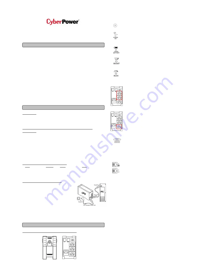
◆
Power Switch
Press the power button to turn the UPS ON or OFF.
◆
Power On Indicator
This LED is illuminated when the utility condition is normal and the UPS outlets are
providing “clean power”, free of surges and spikes.
◆
Using Battery Indicator
This illuminates during utility failure, indicating that the battery is supplying power to
the battery-power supplied outlets.
◆
Boost Indicator
This LED indicates that the UPS is operating in automatic voltage regulation mode.
When the led is illuminated continuously, it indicates that input under-voltage and that
the UPS unit boosts input voltage.
◆
Buck Indicator
This LED indicates that the UPS is operating in automatic voltage regulation mode.
When the led is illuminated continuously, it indicates that input over-voltage and that
the UPS unit bucks the voltage.
◆
Battery Backup and Surge Protection Outlets
The UPS provides battery powered and surge protected
outlets for connected
equipment to insure temporary uninterrupted operation during a power failure and
against surges and spikes.
◆
Surge Protection Outlets
The UPS provides surge protected
only outlet for connected equipments against
surges and spikes.
◆
Serial Port to PC
This port allows connection and
communication from the DB-9 serial or USB port on
the computer to the UPS unit. The UPS communicates its status to the PowerPanel
®
Plus software. This interface is also compatible with the UPS service provided by
Windows 98, Windows ME, Windows NT, Windows 2000, Windows XP,
Windows Server 2003.
◆
Ethernet (RJ-45) Network Protection Ports
These ports are the protection for your computer network cable.
0E


