


Office Tower Series with AVR UPS
OP1500AVR-T4
User Manual
K01-1500A2A
SAFETY WARNINGS
(SAVE THESE INSTRUCTIONS)
This manual contains important safety instructions. Please read and follow all instructions carefully during installation and operation of the unit.
Read this manual thoroughly before attempting to unpack, install, or operate your UPS.
.
CAUTION! To prevent the risk of fire or electric shock, install in a temperature and humidity controlled indoor area free of conductive
contaminants. (Please see specifications for acceptable temperature and humidity range).
CAUTION! To reduce the risk of electric shock, do not remove the cover except to service the battery. No user serviceable parts inside
except for battery.
CAUTION! UPS must be connected to an AC power outlet with fuse or circuit breaker protection. Do not plug into an outlet that is not
grounded. If you need to de-energize this equipment, turn off and unplug the unit.
CAUTION! To avoid electrical shock, turn off the unit and unplug it from the AC power source before servicing the battery or installing a
computer component.
INSTALLING YOUR UPS SYSTEM
UNPACKING
Inspect the UPS upon receipt. The box should contain the following:
UPS Unit
¯
1; PowerPanel Plus Software Disk
¯
1; PowerPanel Software Disk
¯
1; Serial Interface Cable (DB-9)
¯
1; Telephone Cable
¯
1;
User Manual
¯
1; PowerPanel Plus Software User Manual
¯
1; PowerPanel Software User Manual
¯
1.
HOW TO DETERMINE THE POWER REQUIREMENTS OF YOUR EQUIPMENT
1. Insure that the equipment plugged into the battery power-supplied outlets does not exceed the UPS unit’s rated capacity (1500VA/950W).
If rated unit capacities are exceeded, an overload condition may occur and cause the UPS unit to shut down or the circuit breaker to trip.
2. If the power requirements of your equipment are listed in units other than Volt-Amps (VA), convert Watts (W) or Amps (A) into VA by doing
the calculations below. Note: The below equation only calculates the maximum amount of VA that the equipment can use, not what is
typically used by the equipment at any one time. Users should expect usage requirements to be approximately 60% of below value.
TO ESTIMATE POWER REQUIREMENTS
1. Watts (W) x 2.0 = VA or Amps (A) x 120 = VA
2. Add the totals up for all pieces of equipment and multiply this total by 0.6 to calculate actual requirements. There are many factors that can
affect the amount of power that your computer system will require. The total load that you will be placing on the battery-powered outlets
should not exceed 80% of the unit’s capacity.
HARDWARE INSTALLATION GUIDE
1. Connect the equipment to your UPS outlets. Items such as copiers, laser printers, vacuums, space heaters, paper shredders, or other large
electrical devices should not be connected to the UPS. Please assure that the total load of your equipment is less than the maximum total
power capacity of your UPS.
2. Connect your UPS power cord into a two-pole, three-wire grounded
receptacle only. Please avoid using extension cords and adapter plugs.
(To maintain optimal battery charge, leave the UPS plugged in at all
times.)
3. Press the UPS power button to turn it on. The “Power On” indicator will
be illuminated in “Green”.
4. Install your optional software and accessories. To use the software,
simply connect the enclosed serial interface cable to the serial port on
the UPS and an open serial port on the computer.
BASIC OPERATION
FRONT PANEL DESCRIPTION
Power Switch
Press the ON/OFF button to turn the UPS on or off.
Test Switch
This UPS performs a self-test automatically when power is turned on. If the UPS passes the
test, it returns to on-line operation. If the UPS fails the self-test, please recharge the battery
for 4 hours and perform another self-test. If it fails after recharging, please replace the
batteries.
Battery Indicators
These indicators are a visual indication of the battery charge. If battery capacity is under 20%, no indicator LED will illuminate
and the UPS will beep.
Load Level Indicators
These LED indicators are a visual depiction of the UPS load. The load indicator LED will turn orange if the load is between 80
and 100%. If the load is under 20%, no indicator LED will illuminate.
Wiring Fault Indicator
This LED indicator will illuminate to warn the user that a wiring problem exits with the AC outlet, such as bad ground, missing
ground or reversed polarity. If this is illuminated, the user is advised to disconnect all electrical equipment from the outlet and
have an electrician check the outlet to insure proper wiring.
Using Battery Indicator
This illuminates during utility failure, indicating that the battery is supplying power to the battery-power supplied outlets.
AVR Indicator
This LED indicates that the UPS is operating in automatic voltage regulation mode. When the LED is illuminated continuously,
it indicates input over-voltage and the UPS unit bucks the voltage. When the LED is flashed in rotation, it indicates that the
UPS unit is boosting input voltage.
Power On Indicator
This LED is illuminated when the utility condition is normal and the UPS outlets are providing “clean power”, free of surges and
spikes.
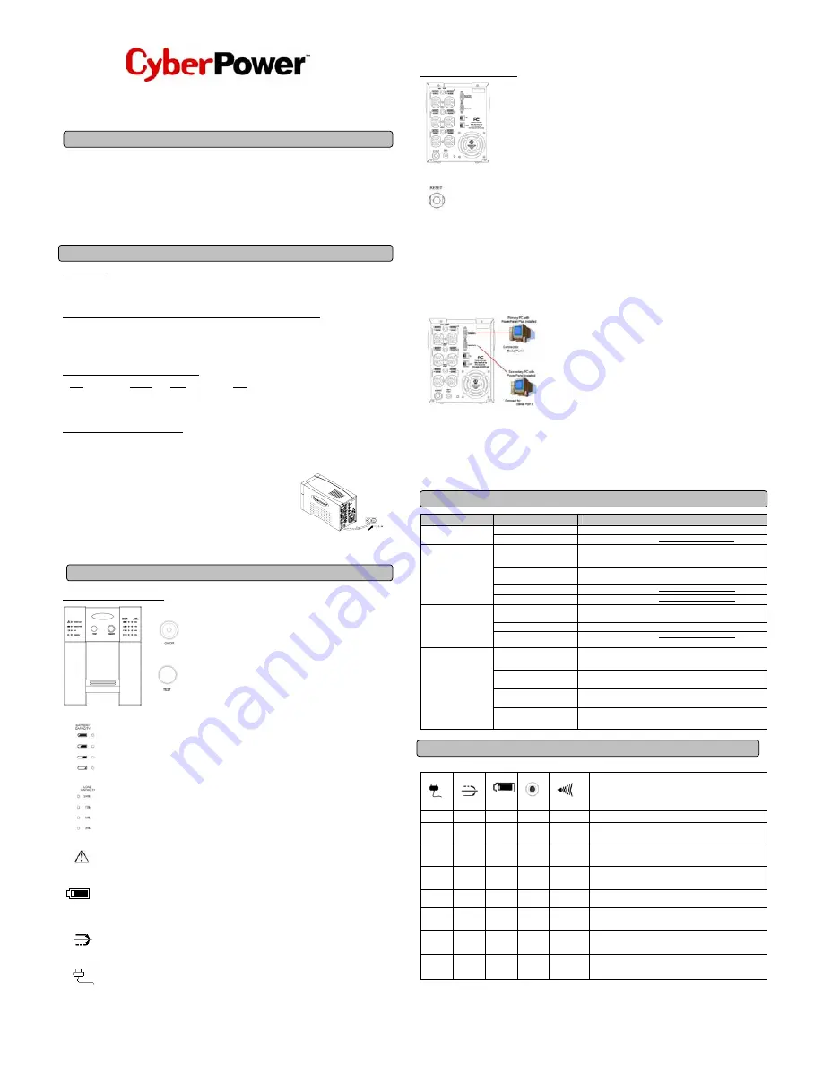
REAR PANEL DESCRIPTION
Battery Backup and Surge Protection Outlets
This unit provides 6 battery-powered, surge-protected and AVR outlets for connected equipment and insures
uninterrupted operation of connected equipment during a power failure.
Circuit Breaker Reset for Overload Protection
Re-settable circuit breakers provide optimal overload protection.
Communication Protection Ports
Combination RJ-45/RJ11 Protection Ports protect your Phone, Fax , Modem, or Ethernet device from surges over the Ethernet orPhone line.
Serial Ports
The OP1500AVR-T4 provides two serial ports to allow connection and communication between the UPS and two computers. This allows the
simultaneous shutdown of two computer systems. These interfaces are also compatible with the UPS service provided by
Windows 2000,
Windows NT, Windows XP, Windows Server 2003 and Mac OS 10X
.
1. The Primary PC
To control the UPS and make any change to the operation of the UPS, please install
the PowerPanel Plus in your primary computer and then connect it to the Serial Port I of
the UPS.
2. The Secondary PC
The secondary computer with PowerPanel installed should be connected to the serial
port II. This PC will shutdown following the user settings in PowerPanel Software when a
power failure occurs.
When a power failure occurs, one of the following shutdown sequences will be executed:
1. If the Primary and Secondary serial ports are both in use: the Primary computer will start to count down (user controlled delay) for shutdown
(User Control delay can be set in the PowerPanel Plus software. Recommended time is 5 minutes). Once the Primary computer is shutdown,
the UPS will signal the Secondary computer and initiate the Secondary to shutdown. The UPS default shutdown time is 2 minutes. Therefore,
it is recommended that Secondary computer is set to shutdown within 1 minute in PowerPanel Software.
2. If only the Secondary serial port is in use: the Secondary computer will shutdown following the user settings in PowerPanel Software.
However, the Secondary computer will not able to signal the UPS to shutdown. Therefore, the UPS will only power off when it is in low
battery.
TROUBLE SHOOTING
Problem
Possible Cause
Solution
Batteries are not fully charged.
Recharge the battery by leaving the UPS plugged in.
The UPS does not perform
expected runtime.
Battery is slightly worn out.
Contact CyberPower Systems at [email protected].
The on/off switch is designed to
prevent damage by rapidly
turning it off and on.
Turn the UPS off.
Wait 10 seconds and then turn the UPS on.
The unit is not connected to an
AC outlet.
The unit must be connected to a 110/120v 60Hz outlet.
The battery is worn out.
Contact CyberPower Systems at [email protected].
The UPS will not turn on.
Mechanical problem.
Contact CyberPower Systems at [email protected].
Circuit breaker is tripped due to
overload
Turn the UPS off and unplug at least one piece of equipment. Wait 10
seconds, reset the circuit breaker and then turn the UPS on.
Batteries are discharged
Allow the unit to recharge for at least 4 hours.
Outlets do not provide
power to equipment
Unit has been damaged by a
surge or spike.
Contact CyberPower Systems at [email protected].
The serial cable is not
connected.
Connect the serial cable to the UPS unit and an open serial port on the back
of the computer. You must use the cable that came with the unit.
The serial cable is connected to
the wrong port.
Check the back of the computer for an additional serial port. Move the
cable to this port.
The unit is not providing battery
power.
Shutdown your computer and turn the UPS off. Wait 10 seconds and turn the
UPS back on. This should reset the unit.
PowerPanel Plus™ is
inactive (all icons are gray).
The serial cable is not the cable
that was provided with the unit.
You must use the cable that was included with the unit for the software and
the unit to be able to communicate.
DEFINITIONS FOR ILLUMINATED LED INDICATORS
Power On
AVR
Using
Battery
Circuit
Breaker
Alarm
Condition
On Off Off Set Off
Normal
On Slow
flash Off
Set
Off
AVR-
Max. boost 13% of input voltage for output regulation while input
voltage is from 5% to 14% under nominal.
ON On Off Set Off
AVR-
Max. buck 11% of input voltage for output regulation while input
voltage is from 8% to 25% over nominal.
Off Off On Set
Two
Beeps
Utility Failure-
The UPS is providing battery power to the Battery-Power
Supplied outlets.
Off Off On Set
Rapid
Beeps
Utility Failure-
The UPS is providing battery power. Rapid beeps
indicate the battery will run out of charge within a few minutes.
On/Off
On/ Off
/Flash
On/Off Set Long
Beep
Overload-
Turn the UPS off and unplug at least one piece of equipment
from the UPS. Wait 5 seconds, reset the circuit breaker and restart the
UPS.
Off Off On Up
Long
Beep
Overload-
Turn the UPS off and unplug at least one piece of equipment
from the UPS. Wait 5 seconds, reset the circuit breaker and restart the
UPS.
Off Off Off Set Off
Surge Protection Malfunction-
Power surge has damaged the unit.
Please contact CyberPower Systems.


