background image

ALPHA AUTOMATIC

COFFEE BREWERS

Wilbur Curtis Co., Inc.

-

S E R V I C E   M A N U A L

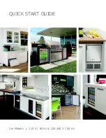
INCLUDES THE FOLLOWING UNITS:

 ALPHA 3X

 ALPHA 3XR

 ALPHA 3XL

 ALPHA 2X

 ALPHA 1X

 ALPHA 6X

Carton Contents

Automatic Coffee Brewer . . . . . . . . . . .
Brewcone . . . . . . . . . . . . . . . . . . . . . . . . .
Paper Filters . . . . . . . . . . . . . . . . . . . . . . . .
Elbow Fitting, 3/8 X 1/4 Flare . . . . . . . . . .

1
1

25

1

Qty

Item

Part Nº

Alpha
WC-3621
CR-10
WC-2401

Table of Contents

Setup . . . . . . . . . . . . . . . . . . . . . . . . . . .
Coffee Requirements . . . . . . . . . . . . .
Coffee Brewing . . . . . . . . . . . . . . . . . .
Maintenance & Cleaning . . . . . . .
Trouble Shooting . . . . . . . . . . . . . . .
Illustrated Parts, Alpha 3X . . . . . . .
Parts List Alpha 3X . . . . . . . . . . . . . .
Parts List Alpha 3XR, 3XL, 2X, 6X . .
Illustrated Parts, Alpha 3XR & 3XL . . .
Illustrated Parts, Alpha 2X . . . . . . . . .
Illustrated Parts, Alpha 6X . . . . . . . . .
Wiring Diagram, Alpha 3X, 3XR, 3XL
Wiring Diagram, Alpha 2X . . . . . . . . .
Wiring Diagram, Alpha 1X . . . . . . . . .
Warranty . . . . . . . . . . . . . .

1
1
2
3

4 - 5
6 - 7
8 - 9

9

10
11
11
12
13
14

Back Cover

WILBUR CURTIS CO., INC.
6913 Acco St., Montebello, CA 90640-5403 USA
Phone: 800/421-6150

Fax: 323-837-2410

Technical Support Phone: 800/995-0417 (M-F 5:30A - 4:00P PST)

    E-Mail: [email protected]

Web Site: www.wilburcurtis.com

Summary of Contents for ALPHA 1X

Page 1: ...Brewing Maintenance Cleaning Trouble Shooting Illustrated Parts Alpha 3X Parts List Alpha 3X Parts List Alpha 3XR 3XL 2X 6X Illustrated Parts Alpha 3XR 3XL Illustrated Parts Alpha 2X Illustrated Parts Alpha 6X Wiring Diagram Alpha 3X 3XR 3XL Wiring Diagram Alpha 2X Wiring Diagram Alpha 1X Warranty 1 1 2 3 4 5 6 7 8 9 9 10 11 11 12 13 14 Back Cover WILBUR CURTIS CO INC 6913AccoSt Montebello CA90640...

Page 2: ... and 3XR have three warmer plates that allow up to three decanters to be kept at serving temperature The hot water faucet lets you draw hot water for tea instant soups chocolate drinks or cup meals even during brew cycle Figure 1 Alpha Brewing System Basic Components WARMERPLATES WATERLEVEL PROBE THERMOSTAT DUMP VALVE HOTWATER FAUCET SPRAYHEAD BREWCONE HEATINGTANK 12CUPDECANTER WATERINLET VALVE WA...

Page 3: ...completely filled the automatic liquid level control will refill the tank 7 Allow about fifteen minutes for the water in the heating tank to come up to proper temperature The READY TO BREW light will turn on when the initial warm up has completed The unit is now ready to brew Because water expands when heated there may be a slight overflow discharge at this time 8 Although this brewer has been tho...

Page 4: ...r plate 4 To start brewing push in the momentary brew switch located on the front panel The brew cycle will take approximately three minutes to complete 5 The warmer plates keep the coffee at serving temperature To activate the warmers push the desired warmer switch located on the front panel COFFEE BREWING l FOLLOWALLBREWINGANDWARMINGINSTRUCTIONS l HOTCOFFEE ALLOWBREWCONETOFINISHDRIPPING l USEONL...

Page 5: ...up and replace it if cracked or leaking 3 The inside of the heating tank should be de limed at least every six months and more often in areas with especially hard water CLEANING Using a daily routine of cleaning the external parts of the Alpha brewing system should maintain its new appearance and better tasting coffee 1 Wipe off any spills dust or debris from the exterior surfaces 2 Clean the outs...

Page 6: ... recurrence of grounding tightly wrap probe with Teflon tape to 1 8 from tip Remove ORANGE wire from probe terminal Do not allow wire to touch any electrical parts Test voltage at terminals of Water Inlet Coil This should read 110 to 220 Volts If there is no voltage go to LLC Board Check board for loose connections or a bad ground If this is okay board is defective Replace LLC Board Turn power off...

Page 7: ...m Water does not flow into Heating Tank Check the brew switch for continuity between terminals 1 white wire and 2 blue wire While pressing the switch If there is no continuity or if you have to push the switch three or four times to read any continuity Replace the brew switch When the timer is activated by the Brew Switch you should read 110 to 120 volts across terminals 6 and A of the timer The R...

Page 8: ... 6 Figure 3 Illustrated Parts List Main View Alpha 3X Shown ALPHA 3X ILLUSTRATED PARTS THIS FIGURE AND FIG 4 SHOW THE ALPHA 3X ALL OTHER ALPHAS ARE SIMILAR EXCEPT WHERE DETAILED FIG 5 6 7 ...

Page 9: ...Figure4 IllustratedPartsList DetailBubbles Alpha3XShown ALPHA ILLUSTRATED PARTS 7 29 ...

Page 10: ...R BREW SCREW 4x3 8 PHIL PAN HEAD LABEL TOP SWITCH PANEL ALPHA 3 SWITCH ON OFF WHITE SWITCH WARMER RED SWITCH BREW GREEN LIGHT BREW READY 120V FAUCET HOT WATER SEAT CUP SILICONE COVER FRONT LOCK NUT 5 8 BRASS SPRAYHEAD RED BUSHING 5 8 SNAP IN COVER BOTTOM BREW CONE UNIVERSAL STANDARD FILTER PAPER 12 CUP BOX OF 1 000 FOOT RUBBER 3 8 16 STUD CORD GRIP STRAIN RELIEF 7 8 POWER CORD 120V ELBOW 1 4 x 3 8...

Page 11: ... 5 16 I D KIT INLET VALVE REPAIR WASHER FLOW VALVE DUMP LEFT 120V 12W COIL FOR DUMP VALVE WC 821 KIT DUMP VALVE FOR WC889 COVER ALPHA 3XR 3XL TOP COVER ALPHA 3XR 3XL BOTTOM LABEL ALPHA 3XR 3XL SWITCH PANEL COVER ALPHA 2X TOP LABEL ALPHA 2X SWITCH PANEL COVER ALPHA 6X TOP COVER ALPHA 6X FRONT COVER ALPHA 6X BOTTOM PART NUMBER WC 5502 WC 2938 WC 4394 WC 4306 WC 917 04 WC 5409 WC 43058 WC 3685 WC 531...

Page 12: ...TRATESTHEDIFFERENCES BETWEEN THE ALPHA 3XR L AND THE ALPHA 3X THE ALPHA 3XR L HAS A PLAIN TOP COVER AND A WIDE BOTTOM COVER THE LABELING ON THE SWITCH PANEL IS ALSO DIFFERENT Figure5 IllustratedParts Alpha3XR 3XL ALPHA3XR ALPHA3XL 64 65 66 8 ...

Page 13: ...RMER SWITCHES ON THE SWITCH PANEL Figure6 IllustratedParts Alpha2X 68 67 THE ALPHA 6X IS BASICALLY AN ALPHA 3XR AND AN ALPHA 3XL LINKEDTOGETHER THISFIGUREILLUSTRATESTHE DIFFERENCESBETWEENTHE ALPHA 6X AND THE ALPHA 3X THE ALPHA 6X HAS A TOTAL OF SIX WARMERS A LARGER TOP COVER CENTERCOVER AND BOTTOMCOVER ALPHA 6X 70 Figure8 IllustratedParts Alpha6X 71 2 ...

Page 14: ... 2 GND 60 120 BLK DRWN WIRING DIAGRAM BOTOM WARMER SWITCH BLK WHT WHT PWR CORD BLK GRN WHT WHITE RED YEL FRONT WARMER SWITCH BROWN WHITE GRY FRONTWARMER ORANGE PROBE RED BOTTOM WARMER 1450WHEATING ELEMENT INLET VALVE YEL ST REARWARMER Figure 9 Alpha 3X 10 Wiring Diagram TOP REAR WARMER SWITCH MODELS 1780 14 8 F Nunez ALPHA 3X 10 ALPHA 3XL 3XR 10 12 BLK BLK BLK BLK WHT WHT WHT WHT BLK BLK BLU BLU W...

Page 15: ...WR CORD WHT BLK BLU RED RED GRY L WHT BLK 2 1 3 T4 T3 T2 T1 WATER LEVEL CONTROL YEL ST BLK WHT BLK YEL 1450W HEATING ELEMENT WHT WHT WHT WHT WHT TIMER RED 2 B 6 A WHT TOPFRONTWARMER BOTTOM WARMER WHT ORG BLK WHT BLK Figure 10 Alpha 2X 10 Wiring Diagram FRONT WARMER SWITCH OFF ON SWITCH BLK 2 1 3 BOTTOM WARMER SWITCH BREW SWITCH 2 1 3 DUMP VALVE INLET VALVE 2 1 3 ...

Page 16: ... 14 BLU RED ...

Page 17: ...THIS PAGE INTENTIONALLY LEFT BLANK ...

Page 18: ...nd cleaning The resetting of safety thermostats and circuit breakers programming and tempera ture adjustments are the responsibility of the equipment owner The owner is responsible for proper cleaning and regular maintenance of this equipment 6 Damaged in transit Equipment damaged in transit is the responsibility of the freight company and a claim should be made with the carrier 7 Abuse or neglect...

Reviews: