DO
GUIDE
SSC Series
Room Availability Hallway Sign, Ceiling Mount
DO
Mount the Assembly
The Crestron
®
SSC room availability hallway sign installs into a conventional drywall or dropped tile
ceiling. After installation, the SSC protrudes 5.18 in (132 mm) below the ceiling surface.
To mount the SSC assembly into the ceiling:
NOTE:
Confirm that there are no fixtures, air ducts, joists, or other possible obstructions in the
mounting location that may impede installation. Use a stud finder tool to help locate joists.
1. After checking for obstructions, trace an outline of the mounting hole directly onto the
drywall ceiling or dropped ceiling tile with the included 2 x 10.4 in (51 x 264 mm) template.
2. Cut around the outline using an appropriate drywall saw to create the mounting hole.
NOTE:
The minimum mounting depth is 1.5 in (39 mm) for use with USB, while the
minimum mounting depth is 2.5 in (64 mm) for use with a Cresnet
®
network connection. For
more information, refer to the product’s table of specifications on the Crestron website.
3. Make all necessary cable connections to the assembly as described in the “DO Connect
the Device” section below.
NOTE:
Observe all local building codes when running cables through the ceiling from the
power source to the installation location.
4. Insert the assembly, top side first, into the mounting hole until the bottom lip of the
assembly engages the bottom of the ceiling.
5. While holding the assembly in position, carefully tighten the four screws attached to the
bottom of the assembly until the swiveling dogs attached to the screws are secured in
place against the ceiling. Do overtighten the screws.
CAUTION:
Set the screwdriver torque to its lowest possible setting to avoid stripping the
swiveling dogs and damaging the ceiling. If removing the assembly from the ceiling, ensure
that the screwdriver rotation is set correctly before untightening the screws.
DO
Connect the Device
The SSC may be powered and controlled by a Crestron TSS-7, TSS-10, TSW-760, or TSW-1060
touch screen via USB, or by a Crestron control system or DMPS3 device via Cresnet. Both
connection methods are described below.
NOTE:
The included USB cable is plenum rated for ceiling installations. If the installation requires
Cresnet cables, use plenum rated Cresnet cables.
•
USB:
Use the included USB cable to connect the SSC to the touch screen. Connect the
cable’s USB A connector to the touch screen and the micro USB connector to the SSC
assembly. Out-of-the-box functionality is established via the touch screen room scheduling
application, with no programming required.
NOTE:
The TSS-7 and TSW-760 may use either PoE (Power over Ethernet) or PoE+ to
supply power to the SSC over USB , but the TSS-10 and TSW-1060 must use only PoE+ to
supply power to the SSC.
DO
Check the Box
QTY
ITEM
PART NUM.
1
Bezel, Ceiling Sign
4526150
1
Cable, USB 2.0, A - Micro B, 15 ft (4.57 m), Plenum Rated
2049072
1
Connector, 4-Pin
2003576
1
Template, Cutout
4526484
•
Cresnet:
Use any standard, plenum rated Cresnet cable and the included 4-pin terminal
block to connect the SSC to a Crestron control system or DMPS3 device. The SSC is
powered and controlled over Cresnet via programming in SIMPL Windows or
Crestron Studio
®
software.
NOTE:
The
CNET ID
button on the bottom of the assembly is used to identify the device on the
network using the Network Tree Device View in Crestron Toolbox™ software. For more information,
refer to the embedded Crestron Toolbox help file.
The brightness of the SSC may be custom programmed as follows:
•
If the SSC is connected to a touch screen, brightness is controlled by sending a custom
property to the touch screen in Crestron Fusion
®
software. For more information, refer to
the embedded Crestron Fusion help file.
•
If the SSC is connected to a control system, brightness is controlled via custom
programming in SIMPL Windows or Crestron Studio. For more information, refer to the
embedded SIMPL Windows or Crestron Studio help files.
DO
Complete the Installation
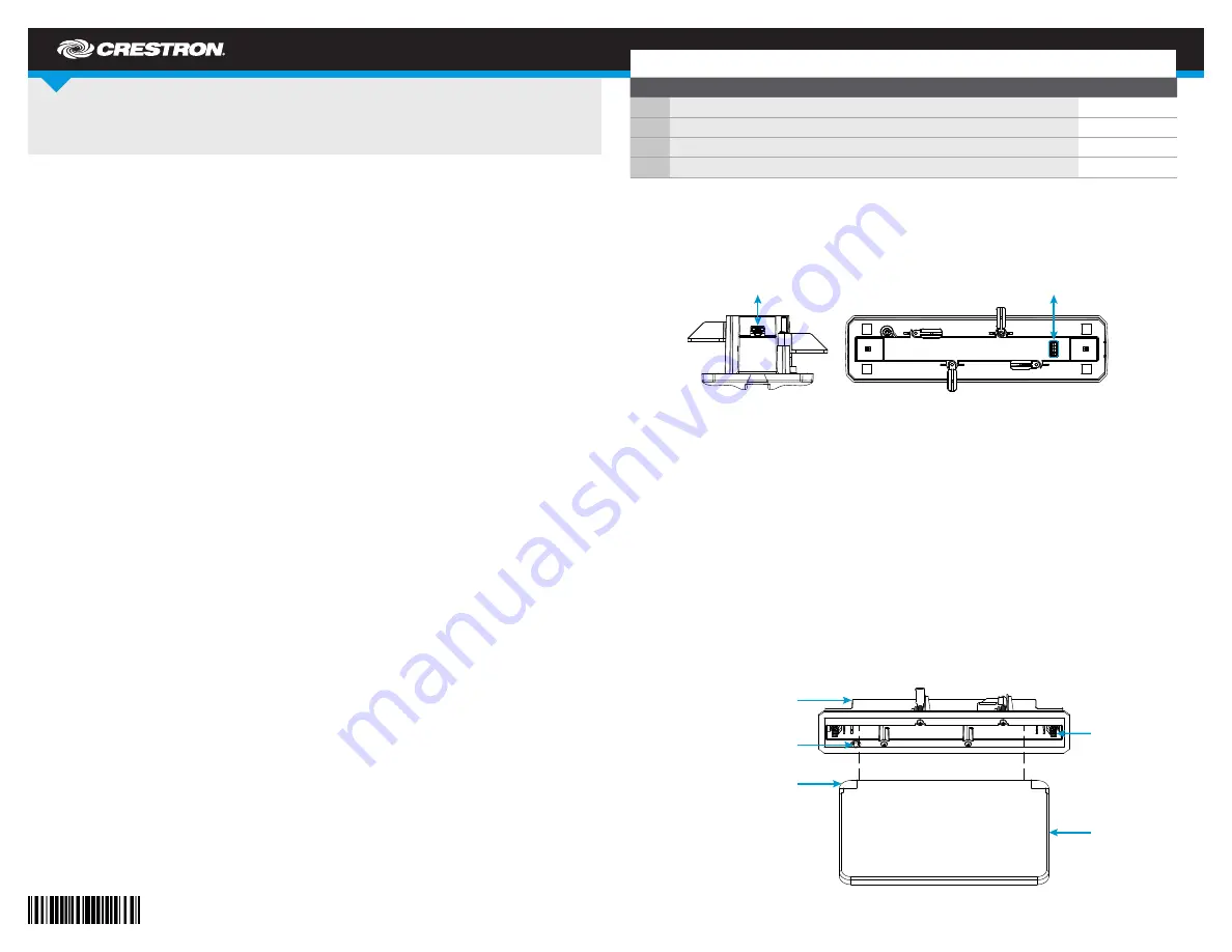
1. Align the acrylic face (included with the SSC kit or purchased separately) with the assembly
so that the side of the acrylic face with the machined recesses is facing away from the side
of the assembly with the CNET ID button.
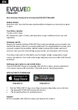
CNET (24 Y Z G):
To Cresnet
®
network device
USB (micro):
To touch screen
Latch
release
tabs (2)
Acrylic
face
Assembly
CNET ID button
(on rear of assembly)
Machined recesses (2)
(in front of acrylic face)