Crestron QuickMedia QM-FTMC, Operations & Installation Manual
The Crestron QuickMedia QM-FTMC is a powerful audio visual solution for meeting rooms. Ensure smooth operations and installation with the free Operations & Installation Manual available for download at manualshive.com. Streamline your AV experience with this cutting-edge technology.
Share
Download


Reviews:
No comments
Related manuals for QuickMedia QM-FTMC
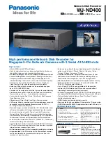
WJND400 - NETWORK DISK RECORDER
Brand: Panasonic Pages: 2
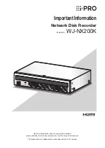
WJ-NX200K
Brand: i-PRO Pages: 22

27PS55S
Brand: Philips Pages: 4

Caruso
Brand: T+A Pages: 56
BVTS4
Brand: Boss Audio Systems Pages: 9

FS5762A1
Brand: Magnavox Pages: 27

TUN-3.7
Brand: Integra Pages: 28

82V42UHD
Brand: Vidao Pages: 40

580006
Brand: Salora Pages: 153

DTA-2196PF
Brand: Haier Pages: 35

LCT50HV
Brand: Olevia Pages: 24

EGT-1
Brand: Emerson Pages: 1

AV-21MT16
Brand: JVC Pages: 22

AV-2186ME
Brand: JVC Pages: 16

AV-21L41
Brand: JVC Pages: 39

AV-20F702
Brand: JVC Pages: 28

AV-21B16
Brand: JVC Pages: 38

AV-2155
Brand: JVC Pages: 24


