

1
quickstart guide
CEN-NVS200
CEN-NV
S20
0
Network Video Streamer
QUICKSTART DOC. 7112A (2030044) 04.11
www.crestron.com
888.273.7876
201.767.3400
Specifications subject to
change without notice.
For details, refer to the latest version of the
CEN-NVS200
Operations & Installation Guide, Doc. 7111.
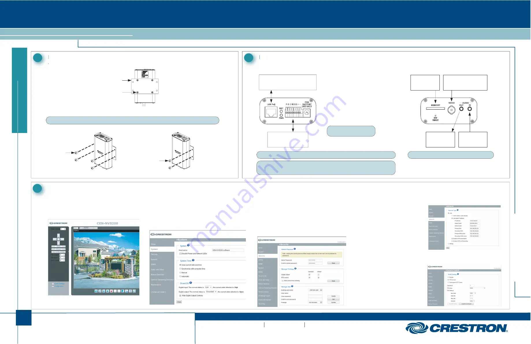
1.
Attach the included mounting bracket.
Mounting the CEN-NVS200
1
1.
In the Crestron Toolbox™ Device Discovery Tool, select
Crestron CEN-NVS200
. The CEN-NVS200 home page will
open.
Congifuring the CEN-NVS200
3
NOTE:
The CEN-NVS200 must be installed in a temperature-controlled environment ranging from 32° to 131° F (0° to 55° C).
If necessary, use the supplied BNC to RCA adapter to connect
the camera.
2.
Mount the CEN-NVS200 on a flat surface or on a rack rail.
CEN-NVS200 Surface Mounting
CEN-NVS200 Rack Mounting
A. Access the Configuration Web Pages
CEN-NVS200 Home Page (Default)
2. Select
Configuration
. The “System” configuration page will
open (refer to section 3B).
B. (Optional) Configure System Settings
C. Configure Security Settings
D. Configure Network Settings
1.
On the “System” configuration page, modify the default host name,
CEN-NVS200
, using a name that is meaningful for your
environment.
2.
Configure DI (Digital Input) and DO (Digital Output) settings.
3. Click
Save
.
“System” Configuration Page
1. Click
Security
. The “Security” configuration page will open.
2. In
the
Admin Password
pane, assign an administrator password,
then
click
Save
at the bottom of the pane. A log-in window will open.
3. Enter
admin
as the user name, then enter the password assigned in step 2.
4. In
the
Manage User
pane, create a user account with
Privilege
set
to
Viewer
, then click
Add
.
“Security” Configuration Page
“Network” Configuration Page
“Camera Control” Configuration Page
1. Click
Network
. The
“Network” configuration
page will open.
2.
Configure a static IP
address and related
network
information.
3. Click
Save
.
E. (Optional) Configure Camera Control Settings
1.
In the column of options on
the left side of the page,
click
Advanced Mode
.
3. Click
PTZ Camera
, then
configure the camera
settings as required.
4. Click
Save
.
Mount the left or right
side of the bracket on
a front or rear rack rail
(right side mounting
shown).
(Bottom) Video and Audio Connections
NOTE:
For connection to a third-party PoE power source, refer to third-party device documentation.
NOTE:
By default, the CEN-NVS200 uses DHCP. If DHCP is not available, the IP address defaults
to 169.254.0.99 and a subnet mask of 255.255.0.0 will be used. If another device uses that
address, another address in the local link address space is selected (169.254.xxx.xxx).
P
= 12 Volts
O
= Digital output
I
= Digital
input
G
= Ground
+
= RS-485, T+/R+
-
= RS-485,
T-/R-
NOTE:
Do not connect anything
to the
X
terminals.
(Top) LAN PoE and 8-Position Terminal Block Connections
LAN PoE:
To 10BASE-T/100BASE-TX
802.3af Compliant Power Source
P O I G X X + -:
To Peripheral Devices,
Sensor, PTZ Camera
MEMORY:
MMC Card Slot
AUDIO OUT:
Line Level
Output
AUDIO IN :
Line Level
Input
VIDEO:
From Camera or Other
Composite Video Source
Hardware Hookup
2
Screws (4) #M3 x 5 mm
( 2022785 )
Mounting Bracket
(2022739 )
Screws (4 )
(Not Supplied)
Rack Mount Screws (2)
(Not Supplied )
NOTE:
The CEN-NVS200 accepts MMC cards up to 16 GB.
2. Click
Camera Control
. The
“Camera
Control”
configuration page will open.


