DO
GUIDE
DO
Check the Box
QTY PRODUCT
PART NUM.
12
Screws
N/A
12
Plugs
N/A
4
Screws
N/A
1
O-ring
N/A
1
Gasket
N/A
5
Waterproof Wire Nuts
N/A
DO
Prepare the Site
1. Dig a hole to bury the speaker. Refer to the illustration that follows for details. Choose a
location that will not fl ood with standing water and where the tube and cap assembly will
not be affected by an in-ground sprinkler system. The installation must comply with all
national and local codes.
NOTE:
The hole must be deep enough to allow a 2 to 4 in (51 to 102 mm) layer of drainage
material (sand and gravel mix or other material approved by local codes) and position the
base of the speaker 13 to 17 in (330 to 432 mm) below ground level.
2. Run the cable from the audio source to a listed and acceptable junction box at the
speaker location while observing all local codes. If the cable is to be run underground, it is
advisable to run it through PVC pipe.
NOTE:
The cable exiting the speaker is approximately 3 ft (1 m) long. Ensure that the
junction box is close enough for the speaker cable to reach inside.
AIR_IGS82T
Air
®
Dual 8” In-Ground Subwoofer
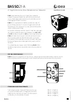
DO
Assemble the Speaker
Refer to the illustration of the Crestron
®
Air
®
Dual 8” In-Ground Subwoofer that follows these
procedures for details on assembling the speaker:
1. Place the supplied O-ring in position on the top
of the
cover.
2. Using a Phillips screwdriver, attach the port tube and cap assembly to the top of the
cover with the four stainless steel screws (A) supplied. Apply even, hand-tight pressure to
compress the O-ring at the port tube base.
3. Ensure that the gasket is securely in position on the underside of the cover (the rounded
side
toward the top
of the
cover). Place the cover on the speaker base assembly, and attach it
using the 12 screws (B) supplied. Torque the screws to a maximum of 19 ft-lbf (25.76 nm).
CAUTION:
If the screws are over-torqued, they may strip the threads of the plastic
housing, and the water-tight integrity of the unit may be compromised.
NOTE:
Do not insert the plugs (C) at this time.
2 to 4 in (51 to 102 mm)
Sand and Gravel Mix Per
Local Code for Drainage
13 to 17 in
(330 to 432 mm)
Ground Level
Local Soil
Stainless Steel
Screws (A)
Screws (B)
Plugs (C)
O-ring
Port Tube and Cap Assembly
Cover
Base Assembly
Gasket
Audio Cable