KBL Series
WIRELESS LED Luminaire
Universal Hook and Cord or Pendant Mount with Sensor
1 of 7
LPN00641X0001A0_B
INSTALLATION INSTRUCTIONS
INSTRUCTIONS D’INSTALLATION
IMPORTANT SAFEGUARDS
When using electrical equipment, basic safety precautions should always be followed including the
following:
READ AND FOLLOW ALL SAFETY
INSTRUCTIONS
1. DANGER
- Risk of shock- Disconnect power before installation.
DANGER
– Risque de choc – Couper l’alimentation avant l’installation.
2. This luminaire must be installed in accordance with the NEC or your local electrical code. If
you are not familiar with these codes and requirements, consult a qualified electrician.
Ce produit doit être installé conformément à NEC ou votre code électrique local. Si vous
n’êtes pas familier avec ces codes et ces exigences, veuillez contacter un électricien qualifié.
3. Suitable for damp location.
Convient aux emplacements humides.
4. Maximum ambient operating temperature: Medium Lumen Package (M) = 50°C and High
Lumen Package (H)= 40°C.
Température ambiante maximale de fonctionnement: Paquet Moyen Lumens = 50°C et
Paquet de Lumen Élevé = 40°C
5. MIN 90°C SUPPLY CONDUCTORS
LES FILS D’ALIMENTATION 90°C MIN.
6. This equipment should be installed and operated with a minimum distance 20cm between the
radiator and your body.
L’équipement doit etre installe d’une facon qu’une distance minimum de 20cm soit maintenue
entre l’emetteur et toute partie du corps.
7. Check to make sure that all input power connections have been properly made and the
module is grounded to avoid potential electrical shock.
8. DO NOT lift luminaire by the power cord or any of the cables connected to the LED heatsink
and LED driver.
9. All electrical connections for the sensor have been made at the factory.
10. The sensor is designed for mounting heights between 8 ft. to 40 ft. (2.4 m to 12.2 m), see
figure 1, 2 and 3 for product specific coverage pattern. The handheld remote unit has a range
of up to 40ft (12.2 m).
11. When mounting heights are above 30ft. (9.1 m), the sensor generally only detects large
objects such as forklift trucks.
12. When the sensor lens assembly is removed the exposed sensor body is sensitive to
electrostatic discharge. Take the necessary steps to avoid possible damage to the sensor
13. Use Class 1 Wiring methods ONLY
SAVE THESE INSTRUCTIONS FOR FUTURE
REFERENCE
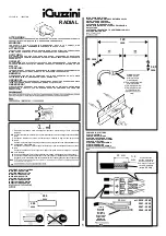
TO INSTALL:
HOOK AND CORD MOUNT
STEP 1:
Push down on retainer spring until top of spring is free of
luminaire hook. See
Figure 1.
STEP 2:
Slide hook into securely mounted customer supplied eye
hanger and return retainer spring to original position.
NOTE:
The luminaire should already be factory set for correct
balance. If necessary, the fixture may be balanced by loosening
the hook adjustment screws on the top of the housing and
sliding the hook as necessary for correct balance. Tighten hook
adjustment screws when finished. See
Figure 1.
STEP 3:
Make wiring connections per the
Electrical Connections
section.
1
Luminaire Hook
Hook Adjustment Screws
Retainer Spring
1/2” (13mm) IP, 0.875”
(22mm) O.D. Knockout
NOTES:
• For each mounting application below,
when mounting to surface ensure that
the mounting surface and customer
supplied hardware is capable of
supporting the weight of the luminaire.
• The center of mounting is NOT the
same as the center of luminaire.