Craftsman 917.293340, Owner'S Manual
The Craftsman 917.293340 is a versatile and reliable tool designed to meet all your outdoor maintenance needs. With our user-friendly Owner's Manual, available for free download at manualshive.com, you can easily access detailed instructions and maximize the potential of your Craftsman product. Get your manual now!
Share
Download


Reviews:
No comments
Related manuals for 917.293340

432118
Brand: Poulan Pro Pages: 40

HST-1003
Brand: RYNO Pages: 23

YCAL0014
Brand: York Pages: 104

sunjoe TJ600E
Brand: SNOWJOE Pages: 48

AROACE
Brand: Yazaki Pages: 16

21A-682J766
Brand: Troy-Bilt Pages: 64

Navigator WWV
Brand: Daikin Pages: 52

ABE 300
Brand: A.B.Energy Pages: 29

ElectraCOOL LA 600
Brand: Advanced Thermoelectric Pages: 24

F 51
Brand: Fort Pages: 28

WER500H
Brand: Weed Eater Pages: 28

V Series
Brand: MP Systems Pages: 47

BX
Brand: Zanotti Pages: 32

BE-910C-DP/DI
Brand: Diamond Pages: 81

GT-35
Brand: Gama Garden Pages: 13

unitrak
Brand: IRUS Pages: 19

PE-AVE 36 Li Basic
Brand: Pattfield Ergo Tools Pages: 128
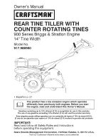
900 Series
Brand: Craftsman Pages: 52


