Craftsman 71-24831, Instruction Manual
The Craftsman 71-24831 Instruction Manual is a must-have for any DIY enthusiast. This comprehensive manual provides step-by-step instructions and invaluable insights to maximize the potential of your Craftsman tool. Download this manual for free from manualshive.com and unleash your creativity with confidence.
Share
Download


Reviews:
No comments
Related manuals for 71-24831

ELEKTRA
Brand: PALSON Pages: 32

GC2800B
Brand: Generac Power Systems Pages: 108

TBL-7800/R
Brand: Tanaka Pages: 86

PB-2155
Brand: Echo Pages: 28

WEB 200
Brand: Weed Eater Pages: 24

FAB-1100
Brand: Superior Pages: 2

JET-3
Brand: JetAir Pages: 29

MVP PLUS Series
Brand: Western Pages: 83

38428
Brand: Toro Pages: 24
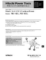
RB 14DL
Brand: Hitachi Pages: 16

41AT4BV-650
Brand: Wolf Garten Pages: 179

38078
Brand: Toro Pages: 28

38540
Brand: Toro Pages: 32

Meteor 97D
Brand: M K Martin Enterprise Pages: 33

MM18
Brand: Maruyama Pages: 28

MD830
Brand: Maruyama Pages: 34

SNC406
Brand: GreenWorks Pro Pages: 44

SN60L00
Brand: GreenWorks Pro Pages: 60


