Craftsman 351.184300, Operator'S Manual
The Craftsman 351.184300, a versatile power tool, offers exceptional performance andprecision. To help you make the most of your tool, we provide a comprehensive Operator's Manual. This manual is readily available for free download at our website, ensuring convenient access to essential instructions and information.
Share
Download


Reviews:
No comments
Related manuals for 351.184300

PHP 500 A1 - 3
Brand: Parkside Pages: 36

PHKP 500 SE - MANUEL 4
Brand: Parkside Pages: 8
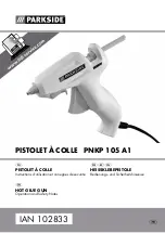
PNKP 105 A1
Brand: Parkside Pages: 36

Druck PV 622
Brand: GE Pages: 55

Matt Gun II
Brand: Freeman Pages: 28

SGY-NR-KITV
Brand: Blue Hawk Pages: 39

FN1665.2
Brand: Paslode Pages: 12

CNW45R
Brand: Paslode Pages: 13

FN1550A26
Brand: Paslode Pages: 20

360Xi
Brand: Paslode Pages: 12

F-350P
Brand: Paslode Pages: 32

502300
Brand: Paslode Pages: 32

901000
Brand: Paslode Pages: 40

FN 1665
Brand: Paslode Pages: 4

CR175C
Brand: Paslode Pages: 36

MHP36
Brand: Meister Pages: 166

FramePro 752XP
Brand: Senco Pages: 2

PHP 500 E3
Brand: Parkside Pages: 34


