background image


CX505 

6” x 89” EDGE BELT SANDER 

User Manual 


Summary of Contents for CX505

Page 1: ...CX505 6 x 89 EDGE BELT SANDER User Manual ...

Page 2: ...der Onto the Stand 8 Motor Drum Guard 9 Fence 9 Auxiliary Table 9 Work piece Stop 10 Belt Tracking 10 ON OFF Switch 11 Test Run 12 Work piece Inspection 12 Connecting to a Dust Collector 12 Table Height Adjustment 13 Tilting the Sanding Head 13 Installing Replacing the Sanding Belt 14 Maintenance 15 Cleaning 15 Lubrication 15 Troubleshooting 16 Parts Diagram 17 Parts List 18 Warranty 24 ...

Page 3: ...s in the immediate vicinity of your machine BE ALERT DO NOT use prescription or other drugs that may affect your ability or judgment to safely use your machine DISCONNECT the power source when changing drill bits hollow chisels router bits shaper heads blades knives or making other adjustments or repairs NEVER leave a tool unattended while it is in operation NEVER reach over the table when the too...

Page 4: ...ng the sander The tiny dust particles produced by the sander can cause serious health problems ALWAYS inspect stock for staples nails knots or any other foreign material before sanding ALWAYS operate the sander in a well ventilated area and use a dust collection system for dust removal whenever possible ALWAYS hold the work piece firmly when sanding When not using the table i e sanding free hand g...

Page 5: ...nd like all power tools proper care and safety procedures should be adhered to Motor 1 1 2 HP 110 V 18 Amps Length of Oscillation 1 8 3 2mm Up 1 8 3 2mm Down 1 4 6 4mm Total Belt Size 6 x 89 152 x 2260mm Belt Speed 3450 RPM Table Size 9 7 8 x 29 5 8 250mm x 751mm Auxiliary Table Size 9 7 8 x 11 78 250mm x 300mm Dust Port One 4 Base Dimensions 21 1 2 Length x 49 Width 546mm x 432mm Overall Dimensio...

Page 6: ...inet Door Lock Powdered Coated Paint 4 Dust Hood ON OFF Switch Sanding Head Tilt Lock Knob 1 1 2 HP Motor Fence Belt Guard 6 x 48 Sanding Belt Work Table Belt Tension Lever Cabinet Door Fence Lock Knobs Motor Drum Guard Dust Hood Lock Knobs Cabinet ...

Page 7: ... sure that the machine is connected to an outlet having the same configuration as the plug If an adaptor plug is used it must be attached to the metal screw of the receptacle To prevent electrical hazards have a qualified electrician ensure that the line is properly wired The sander should be wired with a plug having 3 prongs to fit a 3 prong grounded receptacle as shown in figure 1 Do not remove ...

Page 8: ...ling the stand Slide the stand bottom plate from the top into the stand assembly and install it as shown in figure 3 Secure it to the side brackets using two screws and two washers provided Figure 3 Installing the bottom plate INSTALLING THE SANDER ONTO THE STAND Once the stand is completely assembled and all the screws are tightened properly use a fork lift or get the help of an assistant and lif...

Page 9: ...ence to the table using washers and lock knobs Figure 7 Installing the fence AUXILIARY TABLE The auxiliary table is installed on the right side of the sander when sanding round or curved work pieces To install the auxiliary table Move the dust hood out of the way by loosening the knobs holding it in position Move the dust hood to the back and re tighten the knob to hold it in position as shown in ...

Page 10: ...KPIECE STOP Loosen the knob securing the dust hood in position and move the dust hood out of the way Re tighten the knob to hold the dust hood in position Take the work piece stop and install it by inserting the shaft on the work piece stop into the hole Use a flat washer and a long knob securing the work piece stop onto the sander See figure 11 Figure 11 Installing the work piece stop BELT TRACKI...

Page 11: ...e the switch is in the OFF position the cord is disconnected from the power source Remove the work piece stop and dust hood Loosen the lock nut and turn the adjustment screw a few turns clockwise or anti clockwise as needed using the tool provided Figure 12 Belt tracking adjustment ON OFF SWITCH The ON OFF switch on CX505 features a safety key to prevent from accidental or unauthorized operations ...

Page 12: ...NSPECTION CX505 is designed to sand wood only Do not use this machine to sand metals glass or stone etc Before sanding make sure to inspect the work piece for nails staples small pieces of stone or metal and any other foreign objects that can damage the sanding belt if come in contact Sanding the work piece with this kind of objects can tear the sanding paper For a safe cutting method always inspe...

Page 13: ...e table to your desired height Tighten the knobs and lock the table in position Figure 14 Table height lock knobs TILTING THE SANDING HEAD The sanding head can be adjusted to any angle from 90 to 180 as required for your job To tilt the sanding head Unlock the sanding head by loosening the lock lever under the head shown in figure 15 Tilt the head to the required angle on the head tilt scale Figur...

Page 14: ...g the belt tension handle shown in figure 17 Take the old belt off the drums if already installed and remember the direction of arrows printed on the belt Install the new belt with the direction of arrows pointing to the same direction as the ones on old belt Make sure the belt is in the center of the drums and re tighten the belt tension handle Figure 17 Belt tension handle Once the belt is insta...

Page 15: ...e surface can cause rust The table and other unpainted surfaces of the machine should be cleaned and wiped after every use to make sure there is no moisture against bare metal surfaces LUBRICATION Lubricate the belt tension assembly and the oscillating drum assembly once in 6 months using a small amount of all purpose grease All the bearings in the motor housing and drums are lubricated and do not...

Page 16: ...g Machine vibrates excessively 1 Stand on uneven floor 2 Motor mounts are loose 1 Adjust stand for even support 2 Tighten motor mount belts Abrasive belt keeps tearing 1 Belt is running the wrong direction 1 Observe arrow on the sanding belt Sanded edge not square 1 Table not square to sanding platen 1 Adjust positive stop for 90 Sanding marks on the wood 1 Work piece was held still 2 Wrong grit s...

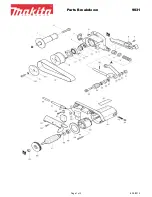
Page 17: ...17 CX505 PARTS DIAGRAM ...

Page 18: ...5 PIN 5 25 1 12 10102024 LOCK HANDLE 3 8 16UNC 1 13 10102023 HAND KNOB 1 14 S0400525 KEY 5 5 25 1 15 S0020416 HEX HD SCR 1 4 20UNC 1 1 16 S0210404 FLAT WASHER 1 4 23 5 17 20101011A TABLE 1 17A S0020510 CAP SCR 5 16 18UNC 1 4 18 20101065 SPECIAL SCR 2 19 S0111000M NUT M10 2 19A S0230308 SPRING WASHER 3 8 2 20 20101013 GUIDE BLOCK 2 21 20101014 FENCE 1 22 20101015 KNOB BOLT 8 12 4 23 20101016 MOTOR ...

Page 19: ...32 32UNC 3 33 10104045 HAND KNOB 1 34 21700001 SANDING TABLE 1 34B 21700002 SANDING TABLE STAND 1 35 21700037 ARBOR 1 36 20101039 KNOB BOLT 8 35 1 37A S0310640 PIN 6 40 1 38 21700004 SPRING 6 40 1 39 20101055 PARTITION RING 1 41 21700005 MOTOR ROLLER BRACKET 1 43 21700052 ROLLER COVER 2 47 20103029C MICRO ADJUST SCREW 1 47A 20103029A MICRO ADJUST NUT 1 48 21700049 RUGULATING PLATE 1 49 S0030304 PH...

Page 20: ...C 3 8 1 61 M0000000 MOTOR 1 62 S0020520 HD HEX SCR 5 16 18UNC 1 1 4 5 63 S0210500 FLAT WASHER 8 5 16 2T 5 16 40 67 L0000154a ELECTRIC CORD 1 69B 21700039 BELT COVER 1 69N 21700013 DUST COVER 1 70 20101002 LIFTING PLATE 2 71 20101024 KNOB BOLT 8 20 3 72 20101040 BRACKET 1 73 20104054 STAND RIGHT RIGHT 2 74 20104053 PARTITION 2 75 20104060G DOOR 1 77 S0211223 FLAT WASHER 12 2 78 S0230506 SPRING WASH...

Page 21: ... 95 S0230300 SPRING WASHER 3 16 10 96 20101050 SUPPORTING ROD 1 100 J0000102 SCALE 1 101 10105052 LABEL 1 103 S0010505 HEX SCREW 5 16 1 1 4 2 104 S0030501 HEX SCREW 5 16 1 4 112 S0030324 PHILIP HD SCR 3 16 1 1 2 3 114 S0110300 NUT 3 16 5 115 L0000005 ELECTRIC CORD 1 117 50203004 KNOB M6 P1 0 2 136 21700018 SUPPORTING BASE 1 137 S0010308 CAP SCR 3 16 3 8 2 138 21700027 BRACKET 1 139 S0020412 HEX HD...

Page 22: ...4 12 3 151 21700017 BEARING BASE 1 152 C1206202 BEARING 6202 1 154 20900049 BEARING COVER 6202 1 155 C1106003 BEARING 6003 1 159 S0400430 KEY 1 161 21700015 FIXED BASE 1 162 S0010510M HEX CAP SCREW 5 163 21700036 BEARING BUSH 2 165 21700021 CAM ECCENTRIC 1 167 21700010 WORM GEAR 1 168 21700020 WORM GEAR SHAFT 1 169 20101048A GRAPHITE PAD 1 170 21700016 SUPPORT SHAFT 2 173 21700011 DUST HOOD LEFT 1...

Page 23: ...89 S0210300a FLAT WASHER 3 16 1 191 S0400425 KEY 4 4 25 1 192 S0230500M SPRING WASHER 11 193 W1017W 2 STRAIN RELIEF BUSHING 2 194 21700032 JOING PLATE 1 195 21700033 SPRING BUCKLE SHAFT 1 196 21700038K DUST COLLECTION 1 202 21700053 SPONGE 1 203 21700054 SPONGE PIECE 1 204 S0300845 CAP SCREW 5 16 18UNC 1 3 4 2 205 90100008a PLATY SPRING 2 ...

Page 24: ...er handy All returned merchandise will be subject to a minimum charge of 15 for re stocking and handling with the following qualifications Returns must be pre authorized by us in writing We do not accept collect shipments Items returned for warranty purposes must be insured and shipped pre paid to the nearest warehouse Returns must be accompanied with a copy of your original invoice as proof of pu...

Reviews: