background image

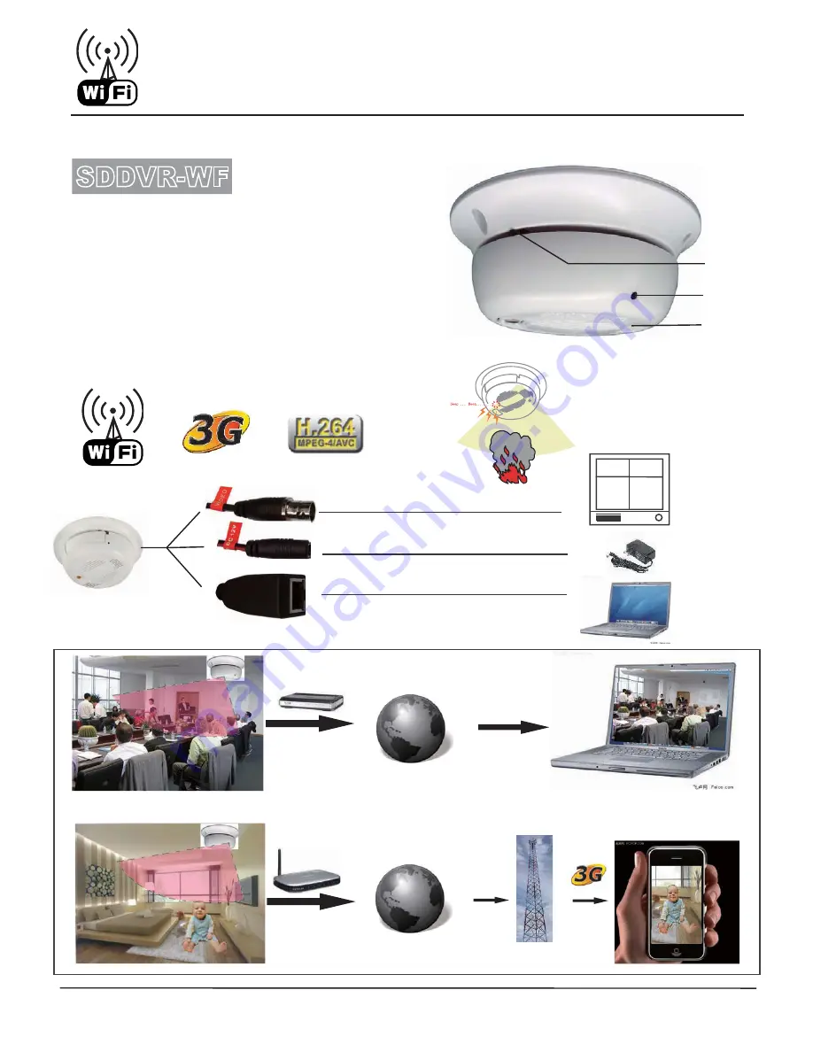
H.264 Wi-Fi IP High Resolution

Smoke Detector Color Camera

3G

 Wifi IP Camera is Accessible from Anywhere in the World by Internet

* 1/3’’ Color CCD High Resolution Camera

* 540 TVL 0.001LUX (SDNR) Slow-shutter

* Audio Video Intercom by Wi-Fi / Ethernet

* H.264 Algorihm hardware compression

* Easy Recording Setup by Internet

* Functional Smoke Detector Camera

* DC12V 1A

MONITOR

Reset

Camera

MIC

Video or DVR

DC12V 1A

Internet

SDDVR-WF

InterNet

Router

InterNet

Wireless Router

* Specifications are subject to change without notice

** Designed  in U.S.A. 

* 3.7mm Pinhole Lens

Summary of Contents for SDDVR-WF

Page 1: ...VL 0 001LUX SDNR Slow shutter Audio Video Intercom by Wi Fi Ethernet H 264 Algorihm hardware compression Easy Recording Setup by Internet Functional Smoke Detector Camera DC12V 1A MONITOR Reset Camera MIC Video or DVR DC12V 1A Internet SDDVR WF InterNet Router InterNet Wireless Router Specifications are subject to change without notice Designed in U S A 3 7mm Pinhole Lens ...

Page 2: ... re now ready to configure your wifi First you need to launch your internet explorer only not compatible with firefox browser Clear out the address bar than type the following ip address in your address bar 192 168 0 233 It will display the login screen before you login please install the ocx plugin first Login name admin Password admin Once you login successfully please click the network setup on...

Page 3: ...1 Network Video Server V1 1 User guide June 18 2007 ...

Page 4: ... them Intellectual property rights All products in this handbook have entire independent intellectual property rights Any individuals or organizations are not allowed to infringe upon any products or reproduce documents of products made by our company Support and service For any technical problems please contact your local vendor If your problem can not be solved immediately the problem will be se...

Page 5: ...3 Network video server user guide v1 1 June 18 2007 Index Index 3 1 Product Overview ...

Page 6: ...ial port parameter setting 26 3 5 4 PTZ management FAQ 26 3 6 Alarm and event management 26 3 6 1 Video motion alarm management 27 3 6 2 Video loss alarm management 28 3 6 3 Sensor input management 29 3 6 4 Sensor output setting 31 3 7 PPPOE DDNS setting 32 3 8 Center platform connection setting 32 3 9 System setting 33 3 10 User rights setting 38 4 Client software operation 39 4 1 System login lo...

Page 7: ...re setting 63 4 7 2 Manual capture 63 4 7 3 Alarm capture 64 4 7 4 Capture images browse 64 4 8 Video record 65 4 8 1 Record setting 65 4 8 2 Timer record 66 4 8 3 Manual record 67 4 8 4 Alarm record 68 4 8 5 Record status checking 72 4 8 6 Video data search 74 4 9 Alarm management 74 4 9 1 Alarm management setting 74 4 9 2 Real time event 76 4 9 3 History event 78 5 Frequent problems 78 6 Appendi...

Page 8: ...TEM SECURITY s 3UPPORT 23 AND 23 INTERFACE WHICH CAN SUPPORT THIRD PARTY 04 DEVICE OR OTHER SERIAL DEVICE 3UPPORT TRANSPARENT TRANSMISSION AND THE PARTICULAR FUNCTION MADE BY OUR COMPANY VIRTUAL MATRIX s 0OWERFUL ALARM MANAGEMENT AND EVENT PROCESSING INCLUDING VIDEO LOST VIDEO MOTION ALARM SENSOR INPUT SENSOR OUTPUT ALARM LINKAGE ALARM AUTOMATIC CONNECTION ALARM LOG CAN HELP YOU HANDLE VARIOUS CON...

Page 9: ...is part For any further enquiry please contact us 1 Please check out all things in the LIST you received ARE THE PACKAGE 2 Please read user handbook carefully before the installation 3 Please switch off all power supply of devices before the installation of 3 62 series video server 4 Check the voltage of power supply to avoid damageS TO THE DEVICE 5 Installation environment please do not use devic...

Page 10: ...r defined usage GND use the output power GND 10 RS232 RS232 connection terminal T sending connection terminal R receiving connection terminal RS232 use output power GND terminal 11 MIC AOUT audio intercom input output connect with passive device 12 VIN video input 1 channel video input standard BNC connector Jack 13 AOUT audio output connect with active device 14 AIN Audio input 1 channel audio in...

Page 11: ...9 Figure 2 2 Installation confirmation Click next there will be a dialogue box Figure 2 3 agreement license Click Yes there will be a dialogue box ...

Page 12: ...10 Figure 2 4 Choose installation folder Choose installation folder click next there will be a dialogue box Figure 2 5 Start to copy files Click Next move to the installation process ...

Page 13: ...llation is finished there will be a dialogue box Figure 2 7 Installation complete Click Finish button client software was installed into the system default directory and there will be a NetView program group on the Start Æ Program of the windows system ...

Page 14: ...onnect DVS with computer via network NVS 6000 video server supports network preview parameter setting and remote control via software and IE Use setting tool When you login the server successfully with IE you can use the convenient setting tool provided by us to configure the video server Click parameter setting with left mouse button configuration tool will pop up a new page displayed as followin...

Page 15: ...bute setting includes video mode color and definition setting ᇹVideo ModeᇺVideo Mode includes PAL and NTSC standard each channel can choose different system please note that the 4 channel server can only choose a same system for each channel ᇹColor SetupᇺColor Setup includes the brightness contrast and hue The left of the setting bar is the minimum value you can easily drag the bar control to chan...

Page 16: ...nel products or 2 channel products support D1 4CIF resolution 4 channel series products support CIF resolution ᇹEncode AudioᇺSelect the encoding audio item of check box if you need audio Uncheck the encoding audio item if you only need video ᇹFrame RateᇺIt means how many frames the encoder is encoding per second For details please refer to table 1 ᇹI Frame InvᇺIt means the number of frame P or fra...

Page 17: ...y of each setting respectively Bit Rate It means the size of stream bit encoding by encoder per second The unit is bit per second This setting is the main factor affects the bandwidth of network and other settings The bandwidth utilizing will increase when the bit rate increase Thus CBR Constant Bit rate setting according to the bandwidth is suitable for the network bandwidth limitation situations...

Page 18: ...alid when the Rate Type is set as VBR Variable Bit rate Definition Definition controls the sharpness of image setting with 4 levels 1 for lowest 4 for highest When the video keep the same quality the higher the definition is the higher the stream rate will be conversely the stream rate will decrease When the stream rate is constant as a low value the higher the definition is the lower the image qu...

Page 19: ...ing condition set according condition worst VBR Variable Bit rate 25 VBR Variable Bit rate worst set according condition set according condition user defined user defined Notice pleas slightly adjust values referring to above reference values according to the system condition You can make necessary adjusting according to the description of each setting if you have strict requirements for the image...

Page 20: ...mage Channel description displays the location with coordinate X 0 720 and Y 0 576 ᇹMask zone settingᇺ This setting achieves the video mask setting function on specific zone Click Covering by left mouse button a setting dialogue box will pop up Then draw a zone where you would like to mask on the image with left mouse button and click Ok the setting is finished If you would like to cancel the mask...

Page 21: ...ideo Mask zone setting 3 3 Audio setting The setting of audio is in the Camera Setup page Clicking ෭ on ႒ in the Encode Audio means the system will encode audio and send encoded audio stream to the client via network ...

Page 22: ...20 Figure 3 5 Audio setting 3 4 System network setting The setting is shown as following figure ...

Page 23: ...DNSᇺPlease enquire your network administrator ᇹMedia Portᇺit is the listening port providing data servers including video and audio stream service and setting service ᇹWeb portᇺit is the listening port providing web service If this setting is changed please login by accessing http IP address web port ᇹTalkback IP settingᇺIt means the IP address of the client This service is valid when you need the...

Page 24: ... set a name 369 Nan Shan Rd for a server located at 369 Nan Shan Rd ᇹSaveᇺClick this button when you finished corresponding setting options 3 5 PTZ COM setting 3 5 1 PTZ device management All of our servers support 64 types of common PTZ protocols Servers use transparent transmission method to manage PTZ device 12V power supply is provided by server for dome plus RS 485 connection The server can c...

Page 25: ...act us for further information about self defined PTZ protocol ᇹAddressᇺInput the address of your PTZ generally the address is configurable ᇹSpeedᇺYou can set the running speed of the dome here ᇹCOM parameterᇺYou need to select the COM parameter between the device and the dome from the pull down menu to ensure the communication ᇹSaveᇺClick this button when you finished corresponding setting option...

Page 26: ...upgrade the protocol if your protocol is a private protocol 3 6 Alarm and event management This section describes the video server alarm parameter setting and the responding when video servers received an alarm Alarm type Combined action Trigger event Alarm Attribute Video motion alarm can combine camera output 1 Images capture and upload to client 2 auto call the speed dome to the appointed prese...

Page 27: ...eal with the alarm according to the local setting Video motion alarm information including server name IP alarm type and time will be saved into log for future inquiry The setting can be set as triggering server automatically login and image opening by client if the client has not connect with network dome when an alarm happened Motion alarm setting instruction It is shown as following figure Figu...

Page 28: ...an they are image dynamic detection zones You can draw the zones with mouse ᇹSensitiveᇺThe sensitivity of motion detection 1 is the highest value Setting skill 1 You can set the detection sensitivity as a higher value to avoid the false alarm causing by small object motions 2 You can set sensitivity as a higher value to avoid the frequent alarm at environment where object motions frequently happen...

Page 29: ...nnect with bells lights beepers etc When video loss event happens system will output on off level to attached devices ᇹAlarm Clear TimeᇺThe alarm output will be canceled after this time 3 6 3 Sensor input management After the sensor alarm service is enabled when the sensor input alarm happened video server will perform following actions Combine the preset sensor to output Capture JPG images and up...

Page 30: ... setting It is shown as following figure Figure 3 10 Sensor input alarm setting ᇹSensor NameᇺThe description of a sensor for easy remembering for example entrance switch room ᇹAlarm Time SetᇺInput value to detect sensor trigger events in specific time according to real conditions ᇹAlarm DurationᇺThe sensor output will be canceled after this time ...

Page 31: ...system must connect with a preset supporting dome and set preset position on the main interface ᇹOutput SetᇺSystem provides 2 channels on off value for user to connect with bells lights beepers etc When sensor trigger event happens system will output on off value to attached devices 3 6 4 Sensor output setting The function of alarm output can automatically trigger specific sensor output on off val...

Page 32: ...ternet connection please set the PPPOE and DDNS here Figure 3 12 PPPOE DDNS setting 3 8 Center platform connection setting Platform connection setting is the necessary setting of the platform surveillance for the front end device please see the following figure ...

Page 33: ...nnect with platform Center IP the IP address of the center platform server Center port the network port of the platform server 3 9 System setting This section introduced system common settings including system time system parameter saving system upgrade system version system restart and system factory settings restore shown as following figure ...

Page 34: ...lient device s time and then click set to synchronize the time of server ᇹSaveᇺClick save to save the parameter into flash of the server unless system will use the previous settings after the restart ᇹServer UpgradeᇺPlease do not use this function except professionals Click browse button to choose the upgrade file as following figure ...

Page 35: ...33 Figure 3 14 Choose upgrade file ...

Page 36: ...gure 3 15 Choose upgrade file Then click Upgrade click Ok button in a pop up box Figure 3 16 Start to upgrade The system will start the upgrade process A progress bar will show the real time upgrade progress ...

Page 37: ...ure 3 17 Upgrading When the upgrade finished there will be a status bar showing Update success The server will restart After the restart you can check if the system is the same version as your upgrade package ...

Page 38: ...gs except network settings and password ᇹRestartᇺ Click Restart button the server will restart 3 10 User rights setting The server supports maximum 5 users Each user has independent rights You can authorize rights to a user with clicking the ෭ on the ႒ The details are introduced following ...

Page 39: ...e this user Only enabled user can login the server otherwise the login will be forbade 4 Client software operation 4 1 System login lock and logout 4 1 1 System login In Windows operation system run NVClient in start Æ program Æ NetView menu the user login window will pop up ...

Page 40: ...38 Figure 4 1 Login Input username password as above figure username and password are not necessary as default value Figure 4 2 Input username and password Click Login to enter the main menu ...

Page 41: ... preview function button servers list and status display 4 1 2 System lock Click button in main menu the client window will be locked and can not continue any operation Re click system lock button a dialogue box will pop up Figure 4 4 Unlock dialogue box ...

Page 42: ...x will pop up Figure 4 5 Logout input dialogue box Input username and password and click ok to logout system 4 2 System setting 4 2 1 Server management Server management will add a server into the local client servers list Click button in main menu and then a local setting window will pop up Enter the normal setting attribute page as the figure ...

Page 43: ...41 Figure 4 6 Server management Add server ...

Page 44: ...P address local display name command port additional information if automatically login enabled if use TRSP channel display video Enabling automatically server login means system will use saved username and password to login the system unless system will pop up a username and password input dialogue to verify the login ...

Page 45: ...ut the server s parameters The factory settings username and password are admin and admin Thus in this example we use admin admin to login Click Ok button to complete the adding process the added servers list can be viewed in the following figure ...

Page 46: ... server adding completed Server modification select server from servers list and click the modify button or double click a server to modify the attribute of a server A window similar as the server adding window will pop up ...

Page 47: ...e server Select a server from the servers list and click the delete button to delete an added server For example in the above figure delete the 102 serve When the delete process completed the system will delete the server in the main menu ...

Page 48: ...Figure 4 12 the result of 102 server deleting 4 2 2 User management Click the button in the main menu to pop up a local setting window and enter the normal setting attribute page please refer to the figure ...

Page 49: ... management Password setting click Set Password button to pop up a username and password setting dialogue box Figure 4 14 Username and password input box Input the new username and password and click Ok button to save it ...

Page 50: ...stem supports servers automatically search and adding by client in a same segment But in the WAN this function is disabled Manual reload user can click NetView with right mouse button and select Refresh from the pop up menu to search servers Figure 4 16 Reload menu 4 3 2 Server login Double click a server in servers list or click server node with right mouse button and select Login Server from the...

Page 51: ... login menu Input username and password in the pop up dialogue box and click connect Figure 4 18 Login dialogue box 4 3 3 Server logout Click server node with right mouse button and select Close Server from the pop up menu ...

Page 52: ...ction hundreds node management 64 image surveillance at one time supporting multi image cyclic switch front user grouping management supporting and grouping switch 4 4 1 Video browse Open a video double click channel in the server list or click channel with right mouse button and select Open Channel shown as following figure ...

Page 53: ...open menu Close the video Method 1 double click the opened video channel in the servers list to close the video Method 2 click a video image with right mouse button and select Close Channel from the pop up menu as following figure ...

Page 54: ...he below of the main menu to change the corresponding icon to Then re click this button to close sound Notice please make sure the video server has already encoded audio and connected with audio input before the play 4 4 3 PTZ control Open the server s channel video select the video image there will be a red frame around the image ...

Page 55: ...nu Control button to control the PTZ Notice please check the PTZ setting errors and PTZ device errors if the control failed Figure 4 23 PTZ control menu 4 4 4 Preset position Open the video server s channel video and select video image ...

Page 56: ...he camera Figure 4 24 Preset control menu 4 5 Audio intercom This function achieves the audio intercom function between client personnel and video server watcher The intercom can be requested from both sides Client side supports audio broadcast enabling intercom with more than two servers 4 5 1 Client request intercom Click button in the main menu an audio intercom dialogue box will pop up as foll...

Page 57: ...55 Figure 4 25 Audio intercom window 4 6 Video grouping viewing 4 6 1 Video grouping setting Click the button in main menu in the pop up local setting menu click grouping switch page as figure ...

Page 58: ...ng menu Add a group In the video grouping setting menu click Add button to pop up the following dialogue box Input the group name and click Ok Figure 4 27 Input group name The group 102 you added will be displayed in the group name list ...

Page 59: ...he Set button or double click there will be a pop up dialogue box Figure 4 29 Server selection Select the server and channel which you want to display and click Ok please see the following figure Notice The server list only displays servers which were added and launched the automatic login setting For the setting method please refer to Server Management ...

Page 60: ...58 Figure 4 30 Server and channel selection Figure 4 31 A image setting completed Follow the above steps to configure the video channel of image display server add multi groups the result will be ...

Page 61: ...59 Figure 4 32 Setting completed menu 4 6 2 Video grouping view Click the in main menu to pop up a configured group list as figure ...

Page 62: ... video of each configured video group according to the time interval Click button in main menu to start the cyclic switch Re click button if you need to stop the cyclic switch 4 7 Image capture The mechanism of image capture is image capture by front side and uploading to client Thus the high definition D1 image can be captured although real time browse is CIF image ...

Page 63: ...mmon Setup attribute page choose the storage disk in the Local Record Disk as following figure Notice system will save files to hard driver D with folders named NVFile if there is not storage selection Figure 4 34 Storage path setting 4 7 2 Manual capture Users can manually capture images while they are viewing video ...

Page 64: ...e button and then click button in main menu with left mouse button Method 3 Select open video image with left mouse button and then use shortcut key F6 4 7 3 Alarm capture Front side alarm automatically capture and image uploading to client to save 4 7 4 Capture images browse Click button in main menu to pop up the local setting menu enter the Local Picture View attribute page to view images ...

Page 65: ...anual record alarm record pre record local remote record search and record cover automatically 4 8 1 Record setting Setting path Click button in main menu to pop up the local setting menu enter the Common Setup attribute page and choose the storage hard driver in the Local Record Disk ...

Page 66: ...pre record and set pre record time in the Environment item Set the record file packing size Figure 4 38 Record packing 4 8 2 Timer record Click button in main menu to pop up the local setting menu enter the On Time Recode attribute page as following figure ...

Page 67: ... please refer to server management for details 2 Please do not close video when you enable the timer record otherwise the system will not record automatically The client must logouts and re logins to restore the timer record 4 8 3 Manual record Start record Method 1 select Record item from the pop up menu by clicking video image with right mouse button as the figure ...

Page 68: ... button F4 Stop record repeat the record start operation to stop record when the system is recording 4 8 4 Alarm record Enable alarm recode setting Click button in main menu to pop up the local setting enter the Common Setup attribute page enable alarm record and set the record time in the Environment ...

Page 69: ...67 Figure 4 41 Enable record setting Enable combined alarm record Enable server video motion combined record as following figure ...

Page 70: ...68 Figure 4 42 Video detecting alarm combined record setting Enable server camera alarm combined record see the figure ...

Page 71: ...69 Figure 4 43 Sensor alarm combined record setting Enable server video loss combined record see figure ...

Page 72: ...splay all combined record settings 4 8 5 Record status checking Method 1 timer record setting click button in main menu to pup up the local setting menu enter the On Time Record attribute page to check if status displaying Running if yes it means it is recording currently as the figure ...

Page 73: ...71 Figure 4 45 Timer record status display Method 2 open the video of the server video channel it means it is recording if there is an icon on the image ...

Page 74: ...rch the path of the driver according to the storage settings 4 9 Alarm management Alarm management includes 1 Enable corresponding channel record 2 Enable local sound alarm 3 Automatically channel pop up 4 Alarm information display 4 9 1 Alarm management setting Enable Enable Sound Alarm ...

Page 75: ...73 Figure 4 47 Local sound alarm Set alarm sound output file Set alarm automatically pop up channel Set pop up electronic map Set alarm pop up information ...

Page 76: ...ime event 1 Normally the Alarm Info button in main menu is displayed as when there is a real time alarm message happened the Alarm Info button will become an alarm status icon The real time alarm information will be record in the alarm information list ...

Page 77: ...75 Figure 4 49 Real time event display 2 There will be an icon in the corresponding video window when a video channel alarm happens Figure 4 50 Video alarm display ...

Page 78: ...lve some problems and will be more stable than the old version software 2ᇬ Contact technical support Please contact technical support or browse our website for technical consultation if the problem is still exists 3ᇬ Frequent problems solutions aᇬcan not visit video server via browser a Possible reason network disconnected Solution Connect network with PC to check if the network is connected well ...

Page 79: ...P address of system is 192 168 55 78 bᇬcan not control dome f Possible reason signal cable is not connected or not connected properly Solution Re connect control cable with dome and server cᇬcan not view normal image g Possible reason OS is Win98 Solution Install DirectX8 0 or later version dᇬcan not use Media player to play the record file Solution Download and install divx common decoder ...

Page 80: ...240 ᇬ QCIF PAL 176 144 NTSC 176 120 ᇬ HALF D1 PAL 704 288 NTSC 704 240 Video in 1 4 channel NTSC PAL auto detect BNC level 1 0Vp p impedance 75Ω 1 4 channel NTSC PAL auto detect BNC level 1 0Vp p impedance 75Ω Frame rate PAL 25F S NTSC 30F S Bit stream type Video stream or complex stream Bit rate 16Kᨺ4M bps Audio in 1channel BNC line in impedance 600Ω 4 channel BNC line in impedance 600Ω Audio out...

Page 81: ...tercom input Mic Network interface One RS232 Serial interface One RS485 Serial interface Alarm input 2 channel Alarm output 2 channel Power supply DC 12V Power consumption Less than 3 5W Working temperature 10ഒ 50ഒ Working humidity 10 90 ...

Page 82: ...pload bandwidth Thus at this point we have to concern about the upload bandwidth for the system design for example for an ADSL with 1 5M download bandwidth the upload bandwidth is less than 512k Thus the upload bandwidth is what we have to concern about mostly for the network design 3ᇬ About the image parameter setting according to networks please refer to image advanced setting in image setting 4...

Reviews: