background image


Manual no. CSMD2-440-CE-ENG-050124 

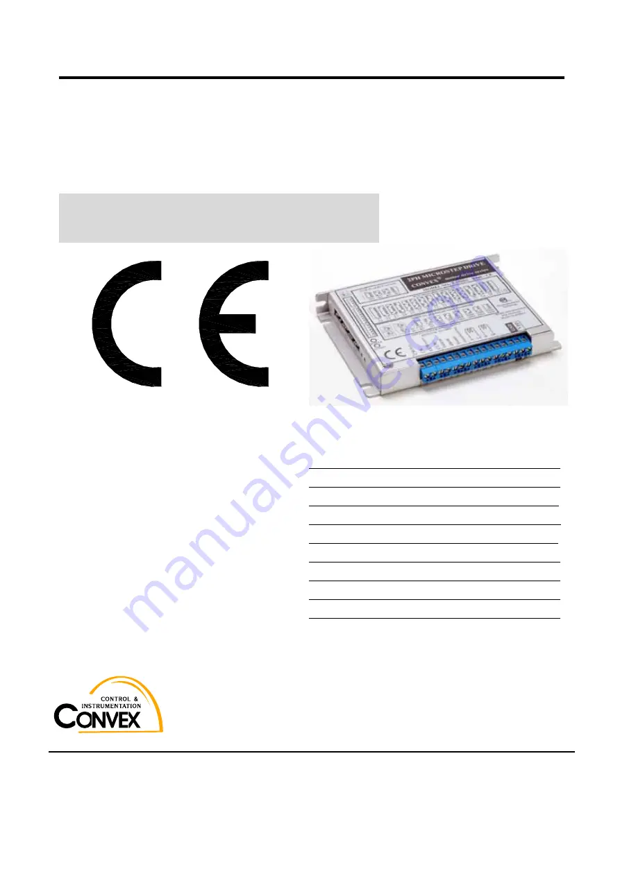
CONVEX Microstep Driver FOR 2PH Step Motor 

CSMD2 –  U440 

(UNIPOLAR DRIVE)


CSMD2 –  B440 

(BIPOLAR DRIVE)


USERS’  GUIDE     


< CONTENTS > 

1. Safety Cautions                                           P.2 

2. Unpacking and Inspection                         P.4 

3. Driver Configuration                                     P.4 

4. Mounting                                                           P.6 

5. Driver Current and Mode set                      P.8 

6. Input Pulse Timing Chart                          P.11 

7. Connection and Wiring                               P.13 

8. Trouble Shooting                                        P.17 

9. Specifications                                             P.19 


Thank you for choosing the Convex Microstep Driver CSMD2 series. 

Please read this manual carefully so that the equipment is used to its optimum.

A copy of this manual should be forwarded to the end user. 

Summary of Contents for CSMD2-B440

Page 1: ...ction P 4 3 Driver Configuration P 4 4 Mounting P 6 5 Driver Current and Mode set P 8 6 Input Pulse Timing Chart P 11 7 Connection and Wiring P 13 8 Trouble Shooting P 17 9 Specifications P 19 Thank you for choosing the Convex Microstep Driver CSMD2 series Please read this manual carefully so that the equipment is used to its optimum A copy of this manual should be forwarded to the end user ...

Page 2: ...ding torque is very small So that when the motor is applied in vertical motion before operation be careful to calculate the load effect CONNECTIONS z Connect correctly according to the connection diagram in this manual Electric shock and fire may occur z The cable should not have excessive force applied to it and should not be bent beyond a 2 5cm radius of curvature during normal operation Electri...

Page 3: ...abrupt stop the motor unnecessarily The regenerated power of motor in sudden stop may break down the drives z When the abnormal operations or emergency occur check the general points listed in the last chapter of this manual z To prevent the electric shock or drive fail use the insulated material to modify dip switches of drive z The motor torque increases according to RUN CURRENT set value Howeve...

Page 4: ...nd properly package this product so that it reaches you defect free and without damage z All packaging materials should be saved and set aside in case a return shipment has to be made The contents may include manual and drive Immediately report any discrepancies to the shipping location 3 Drive Configuration Part name and Its Function Fig 1 drive up side view for part name 3 1 LED indicate name LE...

Page 5: ...nnector Drive out to motor windings For B440 bipolar drive donot connect A_com B_com POWER Power input DC 12 Volt 36Volt Caution Power polarity FG Frame Ground Case of drive is Frame Ground FG 3 3 Dip switch name and function Fig 2 side view for dip switch selection indication name Initial setting function see STOP STOP current level selection 30 100msec after motor stops motor current is down as ...

Page 6: ...drive can be easily contaminated by fluid such as water and oil easily z The place where easy cooling is possible z Do not use this drive under the circumstance of continuous vibration and mechanical shock Mount drive using shock absorbing material z Do not use this drive under the presence of radiation magnetic field or in vacuum z In case when there is unacceptable large noise special cautions a...

Page 7: ...s are fairly tolerant of long lead lengths Should the drive need to be positioned more than 2 m from motor consult the factory for the availability of motors with longer lead lengths 4 3 dimensions Unit mm Fig 3 drive dimension for mounting o n 1 2 3 4 1 2 3 4 5 6 7 8 1 2 3 4 5 o n o n ...

Page 8: ...and result in motor failure z It is recommended that drive RUN current be set as same as rated motor phase current z The motor torque increases according to RUN CURRENT set value However do not set run current larger than motor rated phase current the motor will run roughly and may overheat z The first thing that you must do is set the RUN current on the drive to match the motor that you are using...

Page 9: ...ec after motion is complete This operation is excellent to help control heating and reduce power consumption when not in motion For example Current drive RUN CURRENT is set 3A and STOP CURRENT is set 40 Then the motor current in motion is 3A and 100 msec after motor stop the motor current will become 3A 40 1 2A z When the frequency of drive input pulse is less than 0 1pps 0 1Hz as the run current ...

Page 10: ...t drive resolution is 6400 then it means that drive requires 6400 pulses for motor to rotate 1 turn and 6400pps input made motor turn at the speed of 1 rps revolution per sec z The drive allows the user the versatility to select a microstep resolution that best matches his application requirements For a standard 1 8 step motor there are 8 selectable resolutions that range from 200 to 51200 pulses ...

Page 11: ...h internally with a pull up resistor z Pulse input pulse cw ccw The motor will step on the rising edge of each incoming pulse up to a rate of 500kHz kpps The minimum input pulse width is 1microsecond z Direction Dir A High or open connection on this terminal would cause a clockwise CW rotation of the motor as viewed from the output shaft end When taken Low the direction will be counterclockwise CC...

Page 12: ... the current as follows For example the power supply voltage for pulse input is 5V the voltage of connector is measured as 1 Volt then the diode current is calculated as 5 volt 1 volt 1 2 volt photocoupler diode on voltage 330 ohm 8 5 mA This may cause the malfunction of drive Make the voltage of connector be zero 6 2 drive control signal FAULT out RESET MF in Fig 8 Drive in out signal for control...

Page 13: ...hese wires should be shorter than 1 m z Shield these wires ensure that the shield is taken to a low impedance earth ground z Specially when current resolution of drive is set high and mid or high speed is required more attention is crucially required to wiring pulse input signal z Choose motor and power connection wire sufficiently thick z Do not bundle the control wire and communication cable wit...

Page 14: ...e choose 4A z Power input voltage is 12 36Volt The torque at high speed increases as the magnitude of input voltage Be sure that the peak input voltage is less than 36 volt Also as the magnitude of ripple voltage of input power determines the life of drive so that make the voltage ripple of input power as small as possible z Choose the thick wire for power connection lines Moreover important in wi...

Page 15: ...rate at 100 c maximum allowable case temperature When connected in parallel motors can overheat if operated at high speeds for extended periods of time Actual temperature rise is duty cycle dependent Providing forced air cooling for motors will extend duty cycles but no case should the motor be allowed to exceed the rated maximums z In normal operating condition as the heating in motor and drive d...

Page 16: ...ld be applied with no pulses being fed to the drive The motor will lock into position at its rated static torque If the automatic low power mode has been selected then statistic torque will decrease to STOP level of its rated static torque after 1 msec Once the input pulse rate begins the motor should begin to step in the step direction At this point If the motor does not have any torque or will n...

Page 17: ...otor shaft by putting a drill a chuck on shaft The drill chuck may provide enough inertia to test the motor when it is not loaded In extreme cases a viscous damper may also be needed z If the motor fails to move you should test the motor with an ohmmeter to examine the resistance between the motor connections If the motor is not malfunctioning the source of the problem is probably within the drive...

Page 18: ...nt select switches and verify that the current is set correctly With motor connector removed from the SX use an ohmmeter to measure continuity of motor windings Full and half step modes will cause the motor to run roughly at low speeds Use microstep resolution The motor stalls at high speeds Motor RUN current is not set correctly Motor is undersized for the application Check DIP switches verify th...

Page 19: ...tor 1 phase 200 800 1600 3200 6400 12800 25600 51200 400 500 1000 2000 5000 10000 20000 50000 Dir pulse 1 pulse mode CW CCW 2 pulse mode Reset Motor free photocoupler isolated Alarm out photocoupler isolated Automatic power save Over heat over 70 c over current arm short Power on Alarm 0 c 40 c 0 4 Kg 145 105 20 UNIT mm Factory CONVEX Co Ltd 3F HANIL BLDG 19 13 SUNGSOO 2GA SUNGDONG GU SEOUL KOREA ...

Reviews: