Condair TE Series, Operation And Maintenance Manual
Introducing the Toshiba TE Series - a powerful and feature-packed device designed to cater to all your technological needs. Ensure a smooth and hassle-free experience with the Quick Start Up Manual, providing step-by-step instructions for easy setup. Download your free user manual at manualshive.com and unleash the full potential of your Toshiba TE Series today.
Share
Download


Reviews:
No comments
Related manuals for TE Series

DP1-30E-03
Brand: Gree Pages: 10

MJ-E14CG-S1-SWE
Brand: Mitsubishi Electric Pages: 28

MJ-E14EG-S1-IT
Brand: Mitsubishi Electric Pages: 39
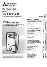
MJ-E130AL-H
Brand: Mitsubishi Electric Pages: 28

MJ-E15BX-S1-IT
Brand: Mitsubishi Electric Pages: 49

MJ-E14CG-S1-IT
Brand: Mitsubishi Electric Pages: 39

MJ-E15BX-S1-IT
Brand: Mitsubishi Electric Pages: 56

MJ-E152AF-H
Brand: Mitsubishi Electric Pages: 28

MJ-E16AX-H
Brand: Mitsubishi Electric Pages: 28

MJ-E16SX-A1
Brand: Mitsubishi Electric Pages: 24

MJ-E160HR-H
Brand: Mitsubishi Electric Pages: 24

MJ-E15BX-A1
Brand: Mitsubishi Electric Pages: 28

MJ-E16V-S1
Brand: Mitsubishi Electric Pages: 18

MIRO-NR07BR
Brand: Miro Pages: 25

DEX Series
Brand: DèLonghi Pages: 8

ElectroVap KIT MC 10
Brand: Devatec Pages: 36

LW 80
Brand: Venta Pages: 8

HUM 282
Brand: Hyundai Pages: 40


