


United States January 2, 2003
Maintenance & Service Guide
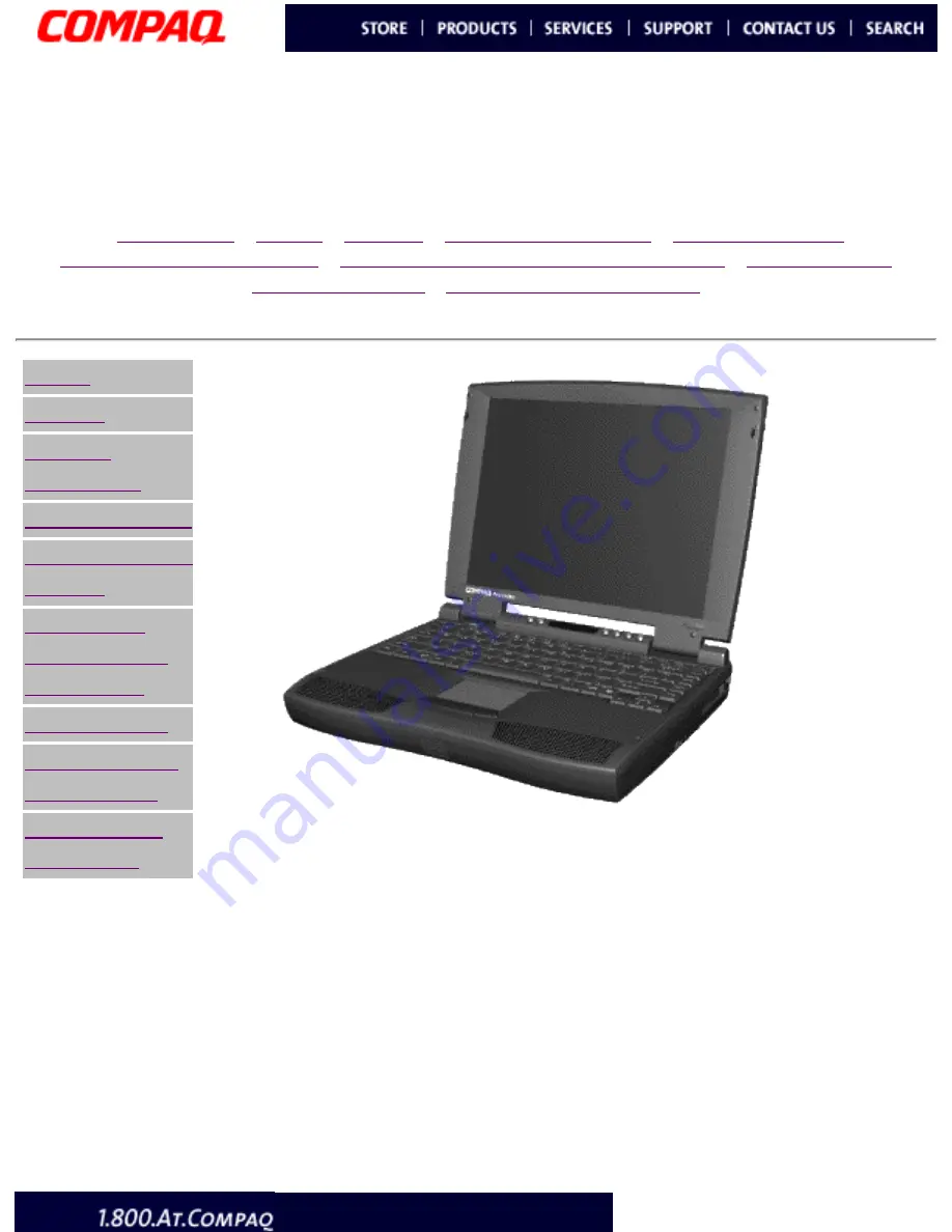
Presario 1800 Series
Models: 1805 and 1810
|
Home Page
|
Notice
|
Preface
|
Product Description
|
Troubleshooting
Illustrated Parts Catalog
|
Removal & Replacement Procedures
|
Specifications
Pin Assignments
|
Battery Pack Operations
Notice
Preface
Product
Description
Troubleshooting
Illustrated Parts
Catalog
Removal &
Replacement
Procedures
Specifications
Connector Pin
Assignments
Battery Pack
Operations
Compaq Presario 1800 Series Portable Computer is a
continuation of the new generation of multimedia portable
computers with an innovative integrated design, outstanding
audio and video, advanced core features, and attractive
styling. This full-function, Pentium II - based series of
portable computers allows full desktop functionality and
additional connectivity via the optional port replicator.
privacy statement
legal notices


