background image

25111-A

Content

Page

300100102902 Rev D

Page 1

This product is covered by one or more U.S.patents or their foreign equivalents.

© 2017

CommScope. 

For patents, see

http://www.commscope.com/ProductPatent/ProductPatent.aspx


All Rights Reserved.
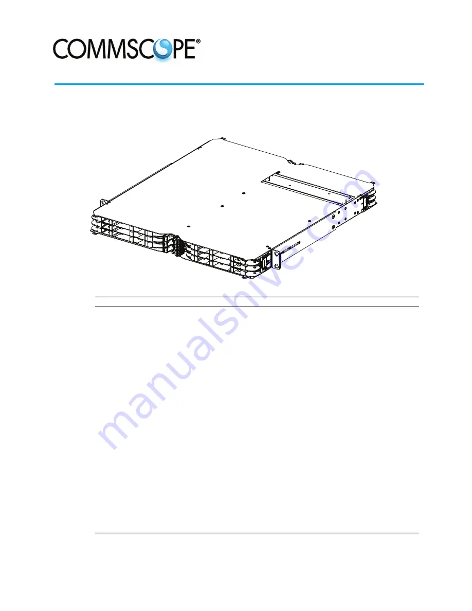
 

User Manual

INTRODUCTION . . . . . . . . . . . . . . . . . . . . . . . . . . . . . . . . . . . . . . . . . . . . . . . . . . . . . . . . . . . . . . . . . . . . . . . . . . . . . 2

RELATED PUBLICATIONS . . . . . . . . . . . . . . . . . . . . . . . . . . . . . . . . . . . . . . . . . . . . . . . . . . . . . . . . . . . . . . . . . . . . . . 3

1

PRODUCT DESCRIPTION . . . . . . . . . . . . . . . . . . . . . . . . . . . . . . . . . . . . . . . . . . . . . . . . . . . . . . . . . . . . . . . . . . 4

1.1

Physical Description . . . . . . . . . . . . . . . . . . . . . . . . . . . . . . . . . . . . . . . . . . . . . . . . . . . . . . . . . . . . . . . 4

1.2

Panel Electronics . . . . . . . . . . . . . . . . . . . . . . . . . . . . . . . . . . . . . . . . . . . . . . . . . . . . . . . . . . . . . . . . . 5

1.3

Status LEDs on Front Panel and Modules . . . . . . . . . . . . . . . . . . . . . . . . . . . . . . . . . . . . . . . . . . . . . . . . . 5

1.4

Specifications . . . . . . . . . . . . . . . . . . . . . . . . . . . . . . . . . . . . . . . . . . . . . . . . . . . . . . . . . . . . . . . . . . . 6

2

UNPACKING AND INSPECTION . . . . . . . . . . . . . . . . . . . . . . . . . . . . . . . . . . . . . . . . . . . . . . . . . . . . . . . . . . . . . . 7

3

INSTALLATION. . . . . . . . . . . . . . . . . . . . . . . . . . . . . . . . . . . . . . . . . . . . . . . . . . . . . . . . . . . . . . . . . . . . . . . . . 7

3.1

Overview . . . . . . . . . . . . . . . . . . . . . . . . . . . . . . . . . . . . . . . . . . . . . . . . . . . . . . . . . . . . . . . . . . . . . . . 8

3.2

Tools and Hardware Needed . . . . . . . . . . . . . . . . . . . . . . . . . . . . . . . . . . . . . . . . . . . . . . . . . . . . . . . . . 8

3.3

Rack Installation . . . . . . . . . . . . . . . . . . . . . . . . . . . . . . . . . . . . . . . . . . . . . . . . . . . . . . . . . . . . . . . . . 8

3.4

Installing the Vertical Cable Guides (VCGs) . . . . . . . . . . . . . . . . . . . . . . . . . . . . . . . . . . . . . . . . . . . . . . .10

3.5

Grounding the Panel . . . . . . . . . . . . . . . . . . . . . . . . . . . . . . . . . . . . . . . . . . . . . . . . . . . . . . . . . . . . . . .13

3.6

Installing the Management Unit . . . . . . . . . . . . . . . . . . . . . . . . . . . . . . . . . . . . . . . . . . . . . . . . . . . . . . .13

3.7

Connecting the Ethernet Cable and AUX Power Cable . . . . . . . . . . . . . . . . . . . . . . . . . . . . . . . . . . . . . . . .14

3.8

Connecting the Control Cable . . . . . . . . . . . . . . . . . . . . . . . . . . . . . . . . . . . . . . . . . . . . . . . . . . . . . . . . .14

3.9

Connecting the Panel to the Quareo Network . . . . . . . . . . . . . . . . . . . . . . . . . . . . . . . . . . . . . . . . . . . . . .15

4

INSTALLING MODULES AND IFC CABLES . . . . . . . . . . . . . . . . . . . . . . . . . . . . . . . . . . . . . . . . . . . . . . . . . . . . . . .15

5

TECHNICAL ASSISTANCE. . . . . . . . . . . . . . . . . . . . . . . . . . . . . . . . . . . . . . . . . . . . . . . . . . . . . . . . . . . . . . . . . .16

Quareo High Density Equipment Panel (HDEP)

TECP-90-801 

 Issue 4 

 October 2017

Содержание Quareo HDEP Series

Страница 1: ...s LEDs on Front Panel and Modules 5 1 4 Specifications 6 2 UNPACKING AND INSPECTION 7 3 INSTALLATION 7 3 1 Overview 8 3 2 Tools and Hardware Needed 8 3 3 Rack Installation 8 3 4 Installing the Vertical Cable Guides VCGs 10 3 5 Grounding the Panel 13 3 6 Installing the Management Unit 13 3 7 Connecting the Ethernet Cable and AUX Power Cable 14 3 8 Connecting the Control Cable 14 3 9 Connecting the ...

Страница 2: ...identifies a possible hazard and then explains what may happen if the hazard is not avoided The admonishments in the form of Dangers Warnings and Cautions must be followed at all times Danger Danger is used to indicate the presence of a hazard that will cause severe personal injury death or substantial property damage if the hazard is not avoided Warning Warning is used to indicate the presence of...

Страница 3: ...e Specifications Caution Installation of the equipment in a rack should be such that air flow to the equipment is not compromised Caution When mounting equipment in the rack make sure mechanical loading is even to avoid a hazardous condition such as loading heavy equipment in the rack unevenly The rack should safely support the combined weight of all equipment it supports Caution Reliable earthing...

Страница 4: ...frastructure Configuration Manager ICM the central system software of the Quareo physical layer management system Refer to Topic 1 2 on Page 5 Figure 1 shows the main physical features of the 1RU panel including the following Access trays hold adapter packs or cabled modules open to front or rear of the panel Access tray doors protect adapter pack or cabled module when access tray is closed Design...

Страница 5: ... Cabled modules ordered separately are also available for this panel For more information see Table 1 1 2 Panel Electronics The Quareo HDEP has electronics that enable it to function by ICM in a Quareo physical management system A typical Quareo network includes both fiber and copper connector panels and non managed representations of the input and output devices such as switches to which cables a...

Страница 6: ...nsert one end of cable Extract one end of cable and so on LED blinking is different for Connect and Disconnect Work Orders For a Connect Work Order step LEDs blink green on the two ports that need to be connected For a Disconnect Work Order step LEDs blink yellow on the two ports that need to be disconnected A LED for an individual port or all LEDs for all ports on a particular module can also be ...

Страница 7: ...g a lightning storm When installing or modifying telephone lines disconnect lines at the network interface before working with uninsulated lines or terminals Caution This equipment is to be installed only in Restricted Access Areas dedicated equipment rooms equipment closets etc in accordance with Articles 110 16 110 17 and 110 18 of the National Electrical Code ANSI NFPA 70 Panel Caution If the p...

Страница 8: ...ack or cabinet or use TrueNet Frame quick fit solution Grounding Secure panel to ground Use 1 Phillips Screwdriver to tighten the 10 32 screws through the ground lug provided into the panel ground PEM nuts Ground cables are NOT provided with the panel Incoming IFC Cable Clamping Use supplied cable clamps and 3 16 standard screwdriver to secure the incoming IFC cable 3 3 Rack Installation The Quare...

Страница 9: ...llips screwdriver type to match mounting screws Locate mounting hardware required MOUNTING BRACKET 12 24 x 1 2 IN SCREW 4 26574 A RACK FRONT FLANGE LOCKWASHER 4 Figure 3 Mounting Panel Shown With 23 Inch Extender Brackets Installed 2 Determine what rack size is being used and reconfigure the mounting brackets if required for the frame or cabinet in which the panel is being installed a For an ETSI ...

Страница 10: ...holes in the mounting brackets with the holes in the equipment rack See Figure 3 on Page 9 6 Secure panel to equipment rack using the appropriate hardware Torque these screws to approximately 27 pound inches 3 1 Newton meters Caution When mounting equipment in the rack make sure mechanical loading is even to avoid a hazardous condition such as loading heavy equipment in the rack unevenly The rack ...

Страница 11: ...VERTICAL CABLE GUIDE VCG TECP 90 801 Issue 4 October 2017 Page 11 2017 CommScope All Rights Reserved Figure 4 Orienting VCG With Panel Shown Here Without Extension Bracket 26576 A INSERTION POSITION Figure 5 Inserting VCG in Panel ...

Страница 12: ...N TECP 90 801 Issue 4 October 2017 Page 12 2017 CommScope All Rights Reserved Figure 6 Pressing VCG Into Position 25409 A GUIDE RAILS FRAME NOT SHOWN FOR CLARITY GUIDE RAILS Figure 7 Make Sure to Insert VCGs Behind Guide Rails ...

Страница 13: ...mately 15 pound inches 1 7 Newton meters Caution Reliable earthing of rack mounted equipment should be maintained Particular attention should be given to supply connections other than direct connections to the branch circuit e g use of power strips 3 Connect the other end of the ground wire to the earth ground conductor Ensure this connection is made using methods and hardware that meets all appli...

Страница 14: ... is not required If both a PoE switch and an AUX power source connection is made the AUX power connection powers the controller If a standard Ethernet non PoE connection is made to the controller the AUX power connection is required to power the controller A PoE switch and an AUX power supply can simultaneously be connected A PoE switch is designed to shut power off when the presence of another po...

Страница 15: ...wn on the Quareo network This procedure is done using a web browser to access the configuration web pages of the panel controller This can be done at the panel by connecting an ethernet cable from a computer to the RJ 45 port of panel controller to gain network access to the controller Once the IP address of the panel is known the user can input the address of the panel controller into the web bro...

Страница 16: ...tructions unique to the various module types are provided through QR code access to the CommScope Field Support Link This online site contains video animations and other information for the specific module being installed The QR code is a label on the front of the panel the Field Support Link is accessed using a visual recognition app on a smart phone 5 TECHNICAL ASSISTANCE http www commscope com ...

Отзывы: