CommScope ION-M8P S, Manual
The CommScope ION-M8P S is an advanced networking device designed for seamless connectivity. Enhance your communication setup with this state-of-the-art product. Easily access the comprehensive user manual for free download from our website, ensuring a smooth installation and optimum performance.
Share
Download


Reviews:
No comments
Related manuals for ION-M8P S

TXWF-PCB-3214
Brand: Ebyte Pages: 6
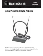
1500254
Brand: Radio Shack Pages: 8

LOOP ANTENNA MIDI
Brand: Ciro Mazzoni Pages: 41

ANT-1000
Brand: Steren Pages: 12

ANT-9040
Brand: Steren Pages: 31

ValuLine VHLP3 Series
Brand: CommScope Pages: 20

DY6
Brand: Hills Pages: 2

FMA120
Brand: Teltonika Pages: 106

OUK00-0494
Brand: 1byone Pages: 2

OUK00-0316
Brand: 1byone Pages: 2

ANT-2015P-M2
Brand: H3C Pages: 8

Sat Fi2
Brand: Globalstar Pages: 2

10M7DX
Brand: M2 Antenna Systems Pages: 8

PAC-12
Brand: Pacific Antenna Pages: 17

222XP30
Brand: M2 Antenna Systems Pages: 6

Portable Antenna
Brand: Snipe Pages: 7

AS-1735/SRC
Brand: Valcom Pages: 19

H-AO8SI
Brand: Hawking Pages: 2


