COMAC Tripla 60B, Use And Maintenance Manual
The COMAC Tripla 60B is a versatile industrial floor scrubber designed to efficiently clean large areas. Ensure optimum performance and longevity by regularly referring to the Use And Maintenance Manual. Download your free manual from manualshive.com to properly care for your investment and maximize cleaning efficiency.
Share
Download


Reviews:
No comments
Related manuals for Tripla 60B

26260000
Brand: Renfert Pages: 52

KFL45BBC
Brand: Krüger Technology Pages: 44

FAE1
Brand: jbc Pages: 20

swingo 1255E
Brand: Taski Pages: 198
4031450
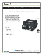
Brand: Quest Engineering Pages: 9

Scrubmaster B75R
Brand: HAKO Pages: 2

ZD-159
Brand: Zhongdi Pages: 2

Comanche 10075270
Brand: Prochem Pages: 15

RC2700 CR2
Brand: Prochem Pages: 29

Ninja Warrior 500 PSI 10070680
Brand: Prochem Pages: 52

Ninja Warrior 200 PSI 10070650
Brand: Prochem Pages: 54

HDV-M903
Brand: HDCVT TECHNOLOGY Pages: 6

ESE201A-W-HV
Brand: Enviroflex Pages: 5

HEPA 700
Brand: Dri-Eaz Pages: 6

125105
Brand: Dri-Eaz Pages: 11

F354
Brand: Dri-Eaz Pages: 12

DefendAir HEPA 500
Brand: Drieaz Pages: 18

HVE-LL Large Loss
Brand: Drieaz Pages: 60


