Com-Power ACS-230-50W, Operation Manual
The Com-Power ACS-230-50W operation manual is available for free download on our website. This comprehensive manual provides detailed instructions on how to effectively operate and utilize the ACS-230-50W product. Access this essential resource at manualshive.com to enhance your user experience.
Share
Download


Reviews:
No comments
Related manuals for ACS-230-50W

Backline Series sheet
Brand: Gallien-Krueger Pages: 16

3300x
Brand: Xtant Pages: 12

VC30
Brand: Laney Pages: 16

MA6100 - SERVICE MANUAL C
Brand: McIntosh Pages: 1

HDA-1832
Brand: Miranda Pages: 4

T2-5001
Brand: Ultimate Pages: 24

P-306
Brand: Onkyo Pages: 9

SA-1073 EQ
Brand: Stam Audio Pages: 8

MPA82000
Brand: MTI Pages: 12

CF-080LS
Brand: Concert Fidelity Pages: 8

ME750-FD
Brand: Mechanics & Electronics Pages: 11

AS-160WRUB
Brand: FONESTAR Pages: 13

Kommander-KA Series
Brand: K-array Pages: 24
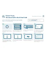
Prisma i35
Brand: Primare Pages: 2

CONCEPT P4
Brand: Balcar Pages: 8

Headphone amp
Brand: Shofar Pages: 2

MA 120
Brand: AMC Pages: 13

KBA15
Brand: Kingsman Pages: 4


