


1
www.colormetrics.info
Colormetrics P1300
Errors excepted; subject to change
www.colormetrics.info
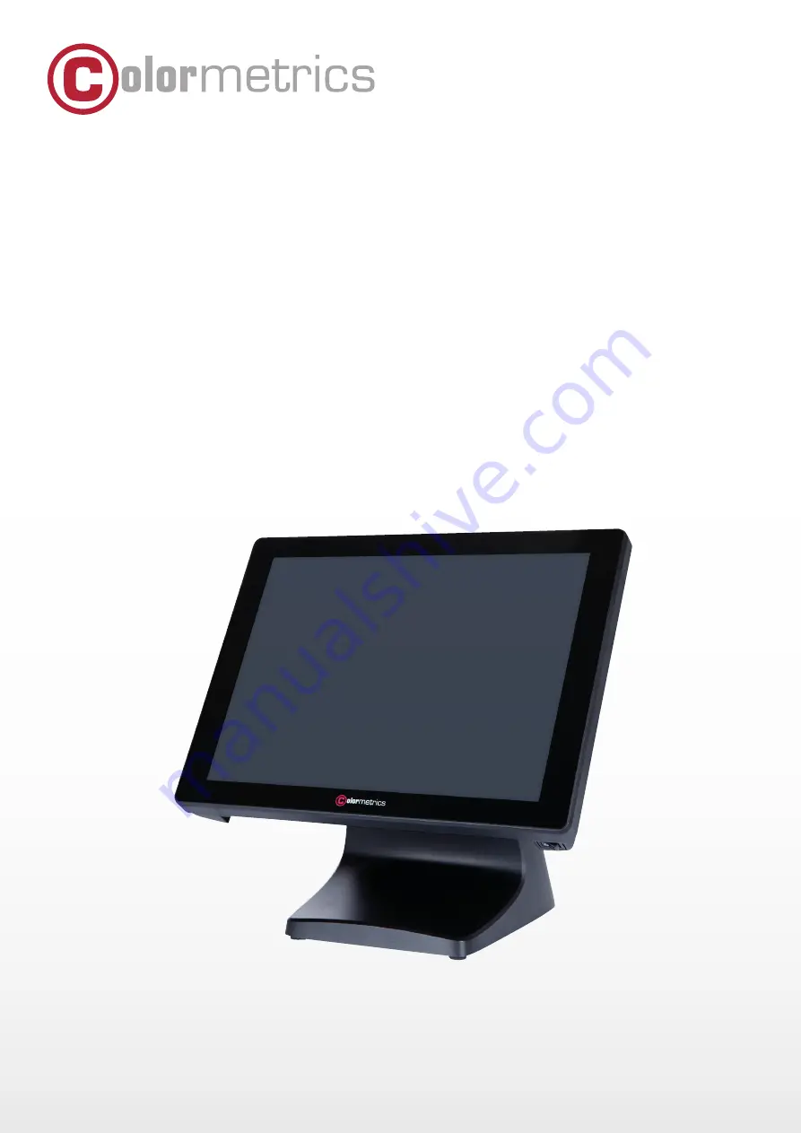
P1300
User Manual
Version 1.0
The Colormetrics P1300 is a high-quality colorimeter designed for accurate color measurement. Ensure proper usage by downloading the free User Manual from our website. This manual provides detailed instructions on how to maximize the functionality of your device. Download it today from manualshive.com.
1
www.colormetrics.info
Colormetrics P1300
Errors excepted; subject to change
www.colormetrics.info
P1300
User Manual
Version 1.0


