
INTRODUCTION
Welcome to a more colorful world brought to you by Color
Kinetics. Chromacore®, our patented core technology, generates
and controls millions of colors and a variety of lighting effects
using a microprocessor to control LEDs. This User Guide contains
important information about installing and operating your new
ColorBlast® 6 fixture safely.
Included In This Box
• ColorBlast 6 with base
• Outdoor junction box gasket for standard US junction boxes
• Water-tight grommet assembly
• 2 8-32 screws for indoor standard US junction boxes with
3.5" center to center mounting holes
• 4 10-24 stainless steel screws for outdoor junction boxes
• Hex key wrench (3/32")
• User Guide
Additional Items Needed
• 4”
Electrical junction box (rated for your application) with 3.5”
center to center distance for mounting locations
• 24VDC Color Kinetics power/data supply
PDS-150e (Item# 109-000008-01) or
PDS-60 24V (Item# 109-000017-00/03)
• Controller - Color Kinetics DMX Controller or DMX compatible
• Color Kinetics Zapi (Item# 103-000005-00, US/103-000005-01, EU)
or Serial Addressing Software (SAS) with iPlayer 2 or
Smart Jack 3
• Adjustable wrench
• Phillips head screw driver
Scope of This User Guide
The goal of this user guide is to explain in an easily understood lan-
guage the necessary steps to install ColorBlast 6 and assure peak
performance. Its intended use is for reference only, by qualified profes-
sionals. This document should never be considered a substitute for any
provisions of a regulation or state, local and/or national codes.
Identification and Warnings of Safety Hazards
In accordance with ANSI Z535.4 the following system of identifying
the severity of the hazards associated with the products is used:
“
danger
” Imminently hazardous situation which, if not avoided,
will result in death or serious injury.
“
warning
” Potentially hazardous situation that, if not avoided,
could result in death or serious injury.
“
caution
” Potentially hazardous situation that, if not avoided, may
result in minor or moderate injury or property damage.
danger
: Ensure that the main power supply is off before install-
ing or wiring ColorBlast 6 and the power/data supply. Failure to
adhere to these instructions will result in death or serious injury.
warning
: ColorBlast 6 and the power/data supply must be
installed by a qualified professional in accordance with NEC and
relevant local codes. Failure to comply can result in death, serious
injury, or property damage.
warning
: Do not attempt to install or use ColorBlast 6 or the
power/data supply until you read and understand the installation
instructions and safety labels. Failure to adhere to these instructions
could result in serious injury or property damage.
caution
: ColorBlast 6 has no serviceable parts. Do not attempt to
open the fixture. Doing so will result in property damage and void
the warranty.
caution
: Do not modify, alter, or attempt to service ColorBlast 6.
Doing so will void the warranty.
caution
: Do not use sharp tools near or on the fixture lens. Doing
so will result in property damage and void the warranty.
caution
: Do not hot swap. Ensure the power supply is off before
connecting or disconnecting fixtures. Hot swapping will result in
property damage and void the warranty.
note
: The instructions and precautions set forth in this installation
guide are not necessarily all-inclusive, all conceivable, or relevant to
all applications as Color Kinetics cannot anticipate all conceivable
or unique situations.
Owner/User Responsibilities
It is the responsibility of the contractor, installer, purchaser, owner
and user to install, maintain, and operate ColorBlast 6 in such a
manner as to comply with all state, local, and national laws, ordi-
nances, regulations, and the American National Standard Institute
Safety Code.
PLANNING THE INSTALLATION
T
he nature of a ColorBlast 6 installation requires planning to ensure
a timely, successful installation with minimal complications and
down time.
Planning Suggestions
When planning a ColorBlast 6 installation, Color Kinetics suggests
doing the following:
• Consult an Electrical Inspector to approve all wiring plans.
• Refer to local and state codes for installation compliance.
• Create a Mapping Grid. Use this grid to record serial numbers
for easy reference and addressing.
• Create a Layout Plan drawing, per Lighting Designer or Architect.
• Employ Color Kinetics Application Engineering Services.
• Get detailed wiring diagrams and additional support from
http://support.colorkinetics.com.
Installation Considerations
When creating your installation plan, consider the following:
• Location of power/data supply in relationship to lights.
• Maximum accumulated cable length for all ColorBlast 6 fixtures
connected to a single PDS-150e is 400 feet. Maximum single
cable run between PDS-150e and ColorBlast 6 is 150 feet.
• Maximum cable length for a ColorBlast 6 fixture connected
to a PDS-60 24V is 150 feet. Therefore, PDS-60 24V must be
located within 150 feet of the furthermost supported fixture.
• Location of fixture and method of mounting. ColorBlast 6 can be
installed indoors or outdoors on a wall, ceiling, or floor. Junction
boxes and mounting methods vary according to location.
INSTALLING COLORBLAST 6
Steps to a Successful Installation
1. Record serial numbers and identify fixtures as you unpack them.
2. Install the power/data supplies.
3. Address the light fixtures.
4. Install ColorBlast 6 fixtures.
5. Make electrical connections.
Recording Serial Numbers
1. As you unpack the fixtures record the serial numbers.
Each ColorBlast 6 has a unique serial number programmed at
the time of manufacture.
2. Write the serial numbers onto a Mapping Grid or use a bar code
scanner along with Color Kinetics Serial Addressing Software
(SAS) to record each serial number. SAS and instructions are
located at www.colorkinectics.com/support/downloads.
3. Using the Layout Plan, assign the fixture to a layout position in
the installation.
4. Using a weatherproof label, identify the fixtures installation posi-
tion based on the Layout Plan. Place the identifying label in an
inconspicuous location noting the order or placement in the instal-
lation. This step not only minimizes installation mistakes, but aids
in post-installation light shows programming.
Installing the Power/Data Supply
Following the Layout Plan, install the power/data supplies
according to state and local codes. Refer to the PDS-150e or
PDS-60 24V Installation Guides for complete instructions.
warning
: Ensure that the power is off before wiring or connecting
fixtures to the power/data supply. Failure to do so can results in
serious injuries or death.
caution
: Never lengthen the ColorBlast 6 cable. Doing so will
result in property damage and void the warranty.
Addressing the Lights
important
: Before you begin the installation, consider the scope of
your lighting application and installation. Your ColorBlast 6 is set
to light address one (1) at the factory. If your application requires
other addresses, set the light addresses using one of the following
addressing tools:
zapi
: Use Color Kinetics Zapi to set the DMX address for each
fixture or set all fixtures to the same DMX address. Refer to the
Zapi User Guide for step-by-step addressing instructions.
sas
(
serial
addressing
software
)
: Use a PC with iPlayer 2, or a
PC with Smart Jack 3 to address the fixtures. Download SAS and
instructions from www.colorkinetics.com/support/downloads.
light
system
manager
(
lsm
)
or
video
system
manager
(
vsm
)
:
Use LSM or VSM software to discover and address all fixtures via
Ethernet. For detailed information on using LSM or VSM, see the
LSM or VSM User's Guides.
note
: All of these tools can be used to address light fixtures either
pre-installation or post-installation (to save time).
note
: For applications using multiple, daisy-chained power supplies,
you can address all lights in the chain by attaching Zapi to the first
power supply in the series.
Setting Individual Addresses
Using the Serial Number mode of Zapi 1.5 or SAS, address each
fixture attached to a power supply or a series of connected power
supplies individually.
1. With power disconnected, connect up to six ColorBlast 6 fixtures
to the power/data supply.
2. Attach the DMX interface (Zapi, iPlayer 2, or Smart Jack 3) to the
DMX IN
port on the power/data supply.
3. Connect power to the power/data supply.
4. Use Zapi or SAS to set the light address for each serial number.
5. Disconnect power and then disconnect the addressed
ColorBlast 6 fixture(s).
6. Repeat steps 1 through 5 for all remaining fixtures.
7. After all fixtures are addressed, disconnect the DMX interface.
Setting the Same Address to Multiple Lights
Using Zapi 1.5, address all fixtures attached to a power supply or
multiple, daisy-chained power supplies.
1. With power disconnected, connect up to six ColorBlast 6 fixtures
to the power/data supply.
2. Attach the Zapi to the
DMX IN
port on the power/data supply.
3. Connect power to the power/data supply.
4. Use Zapi to set the light addresses. All ColorBlast 6 fixtures con-
nected to the power/data supply are addressed simultaneously.
note
: If you are using SAS, you must input each serial number
(address) separately.
5. Disconnect the DMX interface.
Installing ColorBlast 6 Fixtures
This fixture must be installed by a qualified electrician in accor-
dance with NEC and relevant local codes for Class 2 power
sources.
ColorBlast 6 can be installed indoors or outdoors. When mounting
on walls and ceilings, use an electrical junction box rated for your
application.
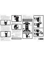
Through-Base Cable Assembly
For all installations where the cable must go through the canopy
base, follow the directions below to prevent cable damage and to
create a water-tight seal for outdoor installations.
1. Screw the liquid-tight fitting into the canopy base. The O-ring
must be seated against the canopy opening to ensure a water-
tight seal.
2. Insert the fixture cable through the dome nut. Loosen the dome
nut if necessary. Pull the cable through the fitting. Leave enough
cable above the fitting to ensure full fixture head rotation.
3. Tighten dome nut to seal the cable. After 24 hours, tighten the
dome nut again to ensure proper sealing force and water-tight
seal. (See Fig. 1.)
Color Kinetics Incorporated
10 Milk street, Suite 1100
Boston, MA 02108 USA
Tel 888 Full RGB
Tel 617 423 9999
Fax 617 423 9998
[email protected]
www.colorkinetics.com
ITEM# 116-000013-00 (White, Frosted)
116-000013-01 (Black, Frosted)
116-000013-02 (White, Clear)
116-000013-03 (Black, Clear)
This product is protected by one or more of the following U.S. Patents and their
foreign counterparts: 6,016,038, 6,150,774, 6,292,901, 6,340,868, 6,777,891,
6,788,011, 6,806,659, 6,969,954, and 6,975,079. Other patents pending.
©2002-2007 Color Kinetics Incorporated. All rights reserved. Chromacore, Chromasic,
CK, the CK logo, Color Kinetics, the Color Kinetics logo, Color Kinetics The Leader in
Intelligent Light, ColorBlast, ColorBlaze, ColorBurst, ColorCast, ColorPlay, ColorScape,
DIMand, Direct Light, EssentialWhite, eW, iColor, iColor Cove, IntelliWhite, iW, iPlayer,
Light Without Limits, Optibin, Powercore, QuickPlay, Sauce, the Sauce logo, and
Smartjuice are either registered trademarks or trademarks of Color Kinetics Incorporated
in the United States and/or other countries.
PUB-000143-00 Rev. 03
Specifications subject to change without notice. Refer to www.colorkinetics.com for the
most recent version.
ColorBlast 6
u s e r
g u i d e
CANOPY BASE
LIQUID-TIGHT
FITTING
O-RING
CABLE
DOME NUT
Fig. 1


