Coldelite UF-253E Gravity and Pump, Operation Manual
The Coldelite UF-253E Gravity and Pump is a versatile frozen dessert machine that combines efficiency and reliability. Ensure optimal performance by following the detailed instructions in the Operation Manual, available for free download at manualshive.com. Perfect your frozen treats with this essential guide.
Share
Download


Reviews:
No comments
Related manuals for UF-253E Gravity and Pump

ALFZ51
Brand: Summit Pages: 12

TF160LW
Brand: STATESMAN Pages: 13

ZNB 3450 S
Brand: Zanussi Electrolux Pages: 24

UOFZ124-S01B
Brand: U-Line Pages: 50
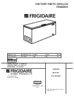
FFC13D7HW0
Brand: Frigidaire Pages: 7

FFC13C7AW2
Brand: Frigidaire Pages: 7

FFC09G7AW0
Brand: Frigidaire Pages: 7

FFC09C3AW1
Brand: Frigidaire Pages: 7
FFC09C7AW
Brand: Frigidaire Pages: 7

FFC09G7AW
Brand: Frigidaire Pages: 7
FFC09M3AW
Brand: Frigidaire Pages: 7

FFC09K0CW
Brand: Frigidaire Pages: 7

FFC13C3AW0
Brand: Frigidaire Pages: 7
FFC09K0CW0
Brand: Frigidaire Pages: 7

FFC1311DW
Brand: Frigidaire Pages: 7

FFC09M5CW
Brand: Frigidaire Pages: 7

FFC13C3AW
Brand: Frigidaire Pages: 7

FFC13C4AW0
Brand: Frigidaire Pages: 7


