Clever Electronics NPM2000, User Manual
The Clever Electronics NPM2000 is a cutting-edge device designed to simplify your electronic needs. For detailed instructions on how to maximize the capabilities of this product, be sure to download the user manual for free from manualshive.com. Unlock the full potential of your NPM2000 with our comprehensive manual.
Share
Download


Reviews:
No comments
Related manuals for NPM2000

TC-107
Brand: Oh!FX Pages: 4

RXYHQ12-36P(8) Series
Brand: Daikin Pages: 78

Expert Power Control 8314
Brand: GÜDE Pages: 111

DMM-40 Series
Brand: Eaton Pages: 4

CV 304
Brand: Schaudt Pages: 10

WB-600-SVCE-12
Brand: WattBox Pages: 12

SVS04-22
Brand: Sollatek Pages: 2

47605-NDP
Brand: Leviton Pages: 2

SIVACON 8PS BD2-S120-B Series
Brand: Siemens Pages: 11

SIMOSEC
Brand: Siemens Pages: 106
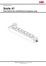
Smile 41 WWWWP
Brand: ABB Pages: 14

TPS 12kv
Brand: Sel Pages: 52

SPDU2100
Brand: SHENZHEN CLEVER ELECTRONIC Pages: 7

Perfect Wave Transport
Brand: PS Audio Pages: 1

PD 3.5
Brand: PS Audio Pages: 8

PerfectWave Power Plant 5
Brand: PS Audio Pages: 18

PowerPlay 8500
Brand: PS Audio Pages: 32

PowerPlay IPC-8000
Brand: PS Audio Pages: 47


