ClearSpan Storage Master Solarguard Series, Assembly Manual
Introducing the ClearSpan Storage Master Solarguard Series, a revolutionary storage solution designed to protect your valuables. Maximizing convenience, our user-friendly manual provides step-by-step assembly instructions to ensure a hassle-free setup. Download your free Assembly Manual today from manualshive.com and unlock the full potential of this exceptional product.
Share
Download


Reviews:
No comments
Related manuals for Storage Master Solarguard Series

L121
Brand: Gainsborough Pages: 2

L120
Brand: Gainsborough Pages: 2
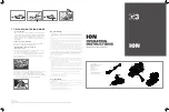
ION
Brand: G3 Pages: 2
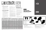
ION
Brand: G3 Pages: 2

G-DRIVE mobile USB
Brand: G-Technology Pages: 13

H-3619
Brand: U-Line Pages: 5

L-FT563PST
Brand: Sunjoy Pages: 5

Carina 28
Brand: Holz-Blech Pages: 20

JAZ TRAVELLER
Brand: Iomega Pages: 2

GAD15264SP
Brand: Endless Summer Pages: 24

100492
Brand: CSPS Pages: 14

T9650 NG
Brand: Real Flame Pages: 57

LITEWEIGHT
Brand: Resilite Pages: 12

CARRIER 20 CART
Brand: LocknCharge Pages: 4

Cove CV-1242
Brand: Outdoor GreatRoom Company Pages: 8

GHESS 9.8-14.4-TH
Brand: GMDE Pages: 50

FPT1880
Brand: Paramount Fitness Pages: 19

BS-T1B
Brand: Zhejiang Longyard Trade Industrial Pages: 18


