background image

1

Revision date: 06.02.09

©2009 ClearSpan™
All Rights Reserved. Reproduction 
is prohibited without permission.

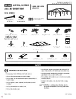
Diagram shows the end wall kit for a 35' wide frame without a door. (Door purchased separately.) Actual panel 
positions and sizes may differ from what is shown in the diagram.


ClearSpan


Twin-Wall Polycarbonate End Panel Kit 

30' Wide & 35' Wide

STK#         

R030A00008 (30' Wide)
R035A00008 (35' Wide)

Summary of Contents for R030A00008

Page 1: ...hout permission Diagram shows the end wall kit for a 35 wide frame without a door Door purchased separately Actual panel positions and sizes may differ from what is shown in the diagram ClearSpan Twin Wall Polycarbonate End Panel Kit 30 Wide 35 Wide STK R030A00008 30 Wide R035A00008 35 Wide ...

Page 2: ...ation of the panels included in this PC package After assembling the end frame continue with these instructions to attach the twin wall polycarbonate panels to the end wall ATTENTION If you purchased an optional door kit consult those instructions and proceed as instructed In most instances the end wall frame and door frame are constructed before end panels are installed This allows for the placem...

Page 3: ...ingress and egress to prevent entrapment WARNING The individuals installing the end wall are responsible for designing and furnishing all temporary bracing shoring and support needed during the assembly process For safety reasons those who are not familiar with recognized construction methods and techniques must seek the help of a qualified contractor REQUIRED TOOLS The following list identifies t...

Page 4: ...N The following graphics and photos will help you identify the different hardware used for the installation of the end panel Some parts are not shown UNPACK AND IDENTIFY PARTS The following steps will ensure that you have all the necessary parts before you begin to install the end panels Unpack the contents of the shipment and place 1 where you can easily inventory the parts Refer to the Bill of M...

Page 5: ...rbonate panels Quick Start section for the location and lengths of each panel The diagrams are located at the back of these instructions ATTENTION Position panels as shown on the panel diagrams Using a panel in the incorrect place can affect the placement of subsequent panels In addition the amount of aluminum profile used between panels may not be adequate if additional seams are created Install ...

Page 6: ...o the girt every 12 on center Do not overtighten screws NOTE Do not use washers on Tek screws when securing the H channel to the girt Install Tek screws in the channel of the aluminum H channel With the first panel attached to the end frame verify 6 that the UV protected surface is toward the outside and repeat the steps to install the next panel A Ground Level 4 x 8 Panel 4 x 8 Panel Girt Diagram...

Page 7: ...of the panel 11 sides and cut H channel to the measured length H channel when installed properly is positioned under the end cap with the panel Use the end cap as a guide to properly cut the upper end of the H channel Set the panel back in place 12 with the UV protected side facing to the outside against the end wall and install the H channel along the edges Top end of the side H channel fits unde...

Page 8: ... channel and installed sidewall panels When installed the panels of the end wall and sidewall meet to form a finished edge at each corner of the building Secure any horizontal section of H channel to the end wall girt using Tek screws See D in the diagram below Measure and cut a section of 104213 profile and install it 16 along the outside of edge of each 6 x 12 panel to complete installation see ...

Page 9: ...good condition Replace damaged panels if needed Check connections and all fasteners to verify that they remain tight Check the contents of the shelter to verify that nothing is touching the polycarbonate panels that could cause damage Inspect the end wall frequently and regularly to ensure that it remains secure and in good repair Replace broken or missing components immediately If the shelter is ...

Page 10: ... Panel 6 x 8 Panel 6 x 8 Panel 6 x 8 Panel 6 x 8 Panel The horizontal dashed lines in the diagrams below show where to attach the panels to the end frame Install Tek screws and washers through the panel and into the end wall girt Evenly space the screws at 12 30 Wide Sample Ground Level 6 x 8 Panel 6 x 8 Panel 6 x 8 Panel 6 x 8 Panel 6 x 12 Panel 6 x 12 Panel 4 x 8 Panel 4 x 8 Panel 4 x 8 Panel 4 ...

Page 11: ...oor installation Diagram below shows the installed sidewall hat channel used for the installation of the sidewall polycarbonate panels of the main building NOTE Install vent tape on the bottom edges of the lower panels and along the top edges of the upper panels Tape the top and bottom of the outer panels marked with an X below All polycarbonate panels to be installed with UV protected surface tow...

Page 12: ...ycarbonate panels to be installed with UV protected surface toward the outside of the shelter X X Install 104213 profile along this edge of the end panel Install 104213 profile along this edge of the end panel If a door was purchased position panels as needed to accommodate the door installation Install door frames before end panels Install the end panels before the sliding door installation Diagr...

Page 13: ...13 Revision date 06 02 09 Notes This page is reserved for customer notes ...

Reviews: