background image

Cisco Systems, Inc.

www.cisco.com


Firepower 8000 Series Getting Started Guide

1

Cisco Firepower 8000 Series Getting 
Started Guide 

For the 81xx, 82xx, and 83xx Firepower and AMP models

Updated:

 February 15, 2016

This guide is organized as follows: 

Package Contents

Deploying the Appliance

Cabling the Device

Installing the Firepower 8000 Series Device

Initial Device Setup

Restoring a Device to Factory Defaults

Scrubbing the Hard Drive

Related Documentation

Package Contents

This section lists the items included with each model. Note that contents are subject to change, and your exact contents 
might contain additional or fewer items. 

Chassis Models

A Firepower 8000 Series device can be delivered on a variety of chassis:

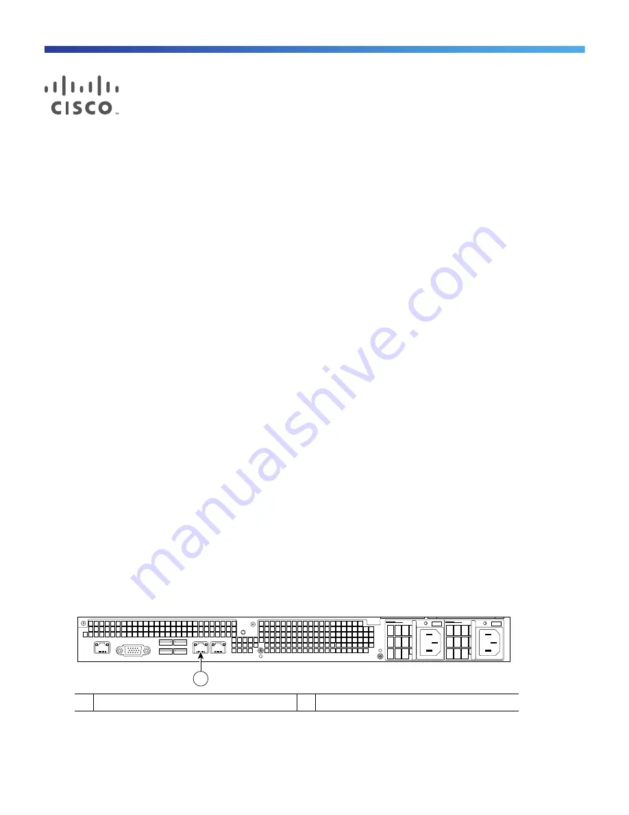
The Firepower 8120/8130/8140 and the AMP8050/AMP8150 are available as 1U appliances and can contain 
up to three sensing modules. The following illustration of the rear of the chassis indicates the location of the 
management interface.

Figure 1

Firepower 

81xx and AMP 8xxx Series Chassis and Management Interface

Firepower 8130 (1U model), this chassis and can contain up to three sensing modules.

1

Management interface

1

373425

Summary of Contents for Firepower 8120

Page 1: ... This section lists the items included with each model Note that contents are subject to change and your exact contents might contain additional or fewer items Chassis Models A Firepower 8000 Series device can be delivered on a variety of chassis The Firepower 8120 8130 8140 and the AMP8050 AMP8150 are available as 1U appliances and can contain up to three sensing modules The following illustratio...

Page 2: ...stacking module You can add up to two stacking kits for a total 8U configuration Firepower 8270 6U stacked model the 40G primary chassis contains two stacking modules and up to five sensing modules Two secondary chassis contains one stacking module You can add one stacking kit for a total 8U configuration Firepower 8290 8U stacked model the 40G primary chassis contains three stacking modules and u...

Page 3: ... fully configured and does not accept a stacking kit Included Items Two power cords per chassis Two straight through Cat 5e Ethernet cables per chassis One rack mounting kit per chassis A combination of Network Modules NetMods as described in the following section Network Modules The sensing interfaces for the Firepower 8000 Series appliances can be delivered with copper or fiber interfaces Cautio...

Page 4: ...Fiber Configurable Bypass NetMod For use only with Firepower 8270 8290 8370 8390 AMP8370 8390 or 40G capable Firepower 8250 8260 8350 8360 or AMP8350 8360 Cable Multiple Fiber Push On MPO connector optical transceivers Passive configurations 1 or 2 Inline configurations 1 Quad Port 1000BASE T Copper Non Bypass NetMod Cable standard copper Passive configurations 1 2 3 or 4 Inline configurations 1 o...

Page 5: ...ould connect a single Firepower 8140 Firepower 8250 or Firepower 8350 AMP8350 Connect the secondary devices to the primary device as indicated in the stack cabling diagram If a secondary device contains sensing interfaces those interfaces are not used After the devices are physically connected to the network segments and to each other use a Firepower Management Center to establish and manage the s...

Page 6: ...cking cable To insert the cable hold the cable end with release tab facing up then insert the keyed end into the port on the stacking module until you hear the latch click into place To remove the cable pull on the release tab to release the latch then remove the cable end Cabling Diagrams ...

Page 7: ...passive or inline cabling configuration The trusted management network a restricted network protected from unauthorized access may have a single secure connection to the Internet for security updates and similar functions but is separate from the rest of your network and is not accessible to hosts used in daily business operations You can connect sensing interfaces to different network segments de...

Page 8: ...n the Firepower Management Center that manages the device to confi gure the device s sensing interfaces as passive inline inline with fail open switched routed or hybrid Use only the interfaces on the front of the device as sensing interfaces See the Firepower 8000 Series Hardware Installation Guide for detailed information on planning your deployment After you have selected a deployment model cab...

Page 9: ... also known as a NULL modem cable or Cisco console cable at any time then configure the remote management console to redirect the default VGA output to the serial port To interact with the appliance use terminal emulation software such as HyperTerminal or XModem The settings for this software are 9600 baud 8 data bits no parity checking 1 stop bit and no flow control Firepower 8000 Series and AMP8...

Page 10: ... to the network segment you want to analyze Fiber Tap If you are deploying the device with an optional fiber optic tap connect the SC plug on the optional multimode fiber cable to the analyzer port on the tap Connect the tap to the network segment you want to analyze Copper Tap If you are deploying the device with an optional copper tap connect the A and B ports on the left of the tap to the netwo...

Page 11: ...ow how the appliance is deployed the setup process is also a good time to perform many initial administrative level tasks including registration and licensing Note If you are deploying multiple appliances set up your devices first then their managing Firepower Management Center The initial setup process for a device allows you to preregister it to a Firepower Management Center the setup process fo...

Page 12: ... device s management interface For a device connected to a computer with an Ethernet cable direct the browser on that computer to the default management interface IPv4 address https 192 168 45 45 For a device where network settings are already configured use a computer on your management network to browse to the IP address of the device s management interface 2 Log in using admin as the username a...

Page 13: ... network settings using the LCD panel Note Enabling this option can represent a security risk You need only physical access not authentication to configure network settings using the LCD panel For more information see Using the LCD Panel on a Firepower Device in the Firepower 8000 Series Hardware Installation Guide Remote Management You must manage a Cisco device with a Firepower Management Center...

Page 14: ...e this mode if your device is deployed inline as part of an access control deployment that is if you want to perform application user and URL control A device configured to perform access control usually fails closed and blocks non matching traffic Rules explicitly specify the traffic to pass You should also choose this mode if you want to take advantage of your device s specific hardware based ca...

Page 15: ...min123 as the password For a device attached to a monitor and keyboard log in at the console If you connected a computer to the management interface of the device using an Ethernet cable SSH to the interface s default IPv4 address 192 168 45 45 The device immediately prompts you to read the EULA 2 Read and accept the EULA 3 Change the password for the admin account This account has Administrator p...

Page 16: ...ice s CLI To register a device use the configure manager add command A unique alphanumeric registration key is always required to register a device to a Firepower Management Center This is a simple key that you specify up to 37 characters in length and is not the same as a license key In most cases you must provide the Firepower Management Center s hostname or the IP address along with the registr...

Page 17: ...y each user but also to limit each person s associated user access role or roles This is especially important on the Firepower Management Center where you perform most of your configuration and analysis tasks For example an analyst needs access to event data to analyze the security of your network but may not require access to administrative functions for the deployment The system includes ten pre...

Page 18: ...commands To access the appliance using the VGA port sudo usr local sf bin configure_console sh vga To access the appliance using the physical serial port sudo usr local sf bin configure_console sh serial To access the appliance using LOM via SOL sudo usr local sf bin configure_console sh sol 4 To implement your changes reboot the appliance by typing sudo reboot The appliance reboots Using the Web ...

Page 19: ...nfiguration and event data on the appliance Although the restore utility can retain the appliance s license network console and Lights Out Management LOM settings you must perform all other setup tasks after the restore process completes Traffic Flow During the Restore Process To avoid disruptions in traffic flow on your network Cisco recommends restoring your appliances during a maintenance windo...

Page 20: ...hts Out Management page 30 Before You Begin Obtain the restore ISO image for the appliance from the Support Site See Obtaining the Restore ISO and Update Files page 20 To restore a Firepower device 1 Copy the image to an appropriate storage medium 2 Connect to the appliance 3 Reboot the appliance and invoke the restore utility What to Do Next Install the ISO image using the procedure in Beginning ...

Page 21: ...n become corrupted Also do not change the names of the files the restore utility requires that they be named as they are on the Support Site Beginning the Restore Process Begin the restore process by booting the appliance from an internal flash drive After you make sure that you have the appropriate level of access and connection to an appliance as well the correct ISO image use one of the followi...

Page 22: ...ess Enter For a serial connection type System_Restore at the prompt and press Enter The boot prompt appears after the following choices 0 Load with standard console 1 Load with serial console 5 Select a display mode for the restore utility s interactive menu For a keyboard and monitor connection type 0 and press Enter For a serial connection type 1 and press Enter If you do not select a display mo...

Page 23: ...e currently installed version of the system until the LILO boot prompt appears For example LILO 22 8 boot System 5 4 System_Restore 3 At the boot prompt start the restore utility by typing System_Restore The boot prompt appears after the following choices 0 Load with standard console 1 Load with serial console 4 Type 1 and press Enter to load the interactive restore menu via the appliance s serial...

Page 24: ...igurations page 29 After you load the configuration skip to menu option 4 Downloading the ISO and Update Files and Mounting the Image page 27 To restore an appliance using the interactive menu use the following steps 1 1 IP Configuration see Identifying the Appliance s Management Interface page 25 2 2 Choose the transport protocol see Specifying ISO Image Location and Transport Method page 25 Tabl...

Page 25: ...e management interface appear 4 Select a method to assign an IP address to the management interface Static or DHCP If you select Static a series of pages prompts you to manually enter the IP address network mask or prefix length and default gateway for the management interface If you select DHCP the appliance automatically detects the IP address network mask or prefix length and default gateway fo...

Page 26: ...sion rules after the appliance is restored to the base version in the ISO image Note that only Management Centers require rule updates The restore utility can only use one system software update and one rule update However system updates are cumulative back to the last major version rule updates are also cumulative Cisco recommends that you obtain the latest updates available for your appliance se...

Page 27: ...Do Next Continue with the next section Downloading the ISO and Update Files and Mounting the Image Downloading the ISO and Update Files and Mounting the Image The final step before you invoke the restore process is to download the necessary files and mount the ISO image Before You Begin Before you begin this step you may want to save your restore configuration for later use For more information se...

Page 28: ...store and press Enter For a serial or SOL LOM connection type System_Restore at the prompt and press Enter In either case the boot prompt appears after the following choices 0 Load with standard console 1 Load with serial console 5 Select a display mode for the restore utility s interactive menu For a keyboard and monitor connection type 0 and press Enter For a serial or SOL LOM connection type 1 ...

Page 29: ...e 30 Saving and Loading Restore Configurations You can use the restore utility to save a restore configuration to use if you need to restore a Firepower device again Although the restore utility automatically saves the last configuration used you can save multiple configurations which include network information about the management interface on the appliance see Identifying the Appliance s Manage...

Page 30: ...ance s web interface to perform the setup For more information see Initial Setup Using the Web Interface page 12 If you deleted license and network settings you must configure the appliance as if it were new beginning with configuring it to communicate on your management network See Installing the Firepower 8000 Series Device page 9 Note that deleting license and network settings also resets displ...

Page 31: ...ecause of this Cisco recommends you configure the Firepower 7050 BMC with a static IP address Alternately you can disconnect the network cable and reconnect it or remove and restore power to the device to force renegotiation of the link Before you can restore an appliance using LOM you must enable LOM for both the appliance and the user who will perform the restore Then use a third party Intellige...

Page 32: ...erial Port then specify the LOM IP address netmask and default gateway or use DHCP to have these values automatically assigned Note The LOM IP address must be different from the management interface IP address of the appliance To enable LOM capabilities for a Firepower System user 1 Select System User Management then either edit an existing user to add LOM permissions or create a new user that you...

Page 33: ...d verify Please refer to the DoD document for additional constraints Caution Scrubbing your hard drive results in the loss of all data on the appliance which is rendered inoperable You scrub the hard drive using an option in the interactive menu described in Using the Interactive Menu to Restore an Appliance page 23 To scrub the hard drive 1 Follow the instructions in one of the following sections...

Page 34: ...Related Documentation Firepower 8000 Series Getting Started Guide 34 ...

Reviews: