background image

Maintaining the Server Chassis

This chapter contains information about system LEDs and supported component installation or replacement.

Status LEDs and Buttons, on page 1

Preparing For Component Installation, on page 6

Opening the Chassis Compartment Covers, on page 9

Removing and Replacing Components, on page 11

Status LEDs and Buttons

This section contains information for interpreting LED states.
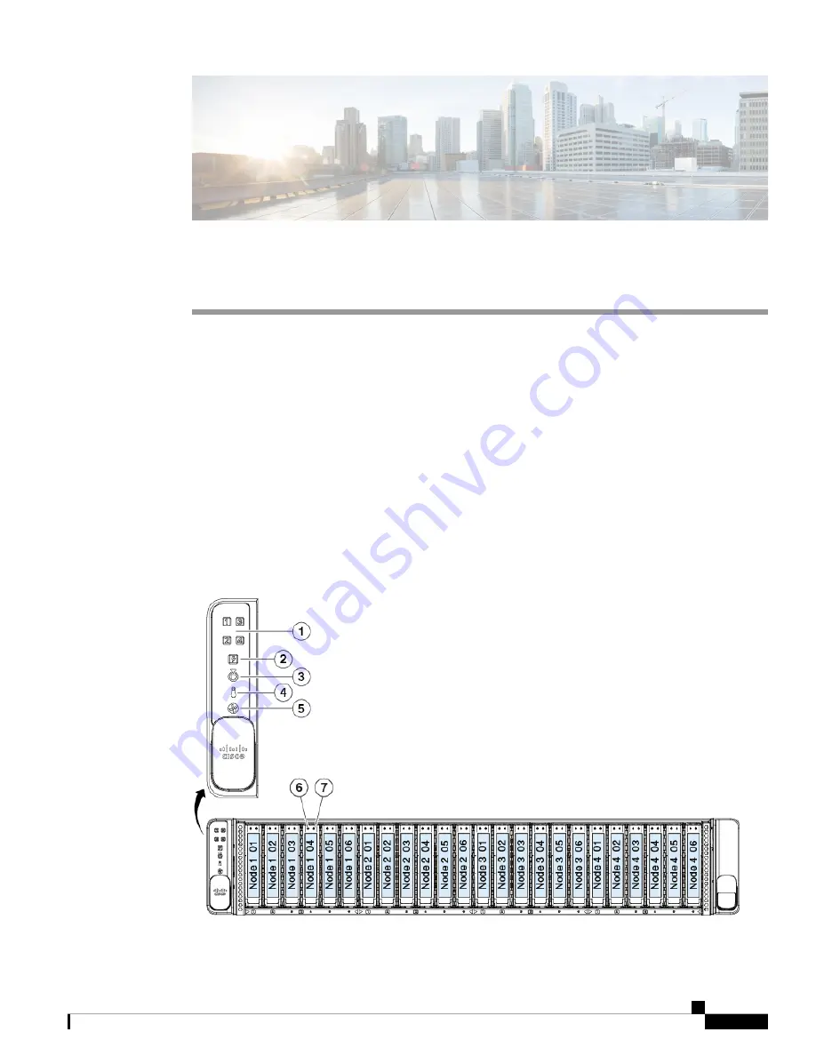
Front-Panel LEDs

Figure 1: Front Panel LEDs

Maintaining the Server Chassis

1

Summary of Contents for C4200

Page 1: ...Status LEDs and Buttons on page 1 Preparing For Component Installation on page 6 Opening the Chassis Compartment Covers on page 9 Removing and Replacing Components on page 11 Status LEDs and Buttons This section contains information for interpreting LED states Front Panel LEDs Figure 1 Front Panel LEDs Maintaining the Server Chassis 1 ...

Page 2: ...numbered node bays 1 Green All power supplies are operating normally Amber steady One or more power supplies are in a degraded operational state Amber blinking One or more power supplies are in a critical fault state Power supply status 2 Activating the locator beacon on any installed compute node activates this chassis locator beacon Off The unit identification function is not in use Blue blinkin...

Page 3: ...ate drive SSD drive tray LEDs have different behavior than SAS SATA drive trays Note 7 SAS Off The drive is not in use and can be safely removed Green The drive is in use and functioning properly Green blinking the driver is initializing following insertion or the driver is unloading following an eject command Amber The drive has failed Amber blinking A drive Locate command has been issued in the ...

Page 4: ...ns Boot failure Fatal CPU and or bus errors detected Fatal uncorrectable memory errors Excessive thermal conditions Node Health Status 1 Off There is no AC power to the node Amber The node is in standby power mode Power is supplied only to the Cisco IMC and some motherboard functions Green The node is in main power mode Power is supplied to all node components Node Power button Node Power status O...

Page 5: ...ain power on 12 V standby power on Amber blinking Warning threshold detected but 12 V main power on Amber solid Critical error detected 12 V main power off for example over or under current over voltage or over temperature failure Amber solid If no AC input is supplied to one power supply the LED lights amber from the shared system standby bus Power supply status One bi color LED each power supply...

Page 6: ...ire the following tools for removal or installation 1 Phillips head screwdriver for opening the supercap compartment cover An electrostatic discharge ESD strap or other grounding equipment such as a grounded mat is recommended to protect components Shutting Down and Removing Power From the System Chassis Power The C4200 system chassis does not include a physical power button All of the component r...

Page 7: ...ower button LED on the face of the compute node Amber The node is already in standby mode and you can safely remove it from the chassis Green The node is in main power mode and must be shut down before you can safely remove it from the chassis Step 2 Invoke either a graceful shutdown or a hard shutdown To avoid data loss or damage to your operating system you should always invoke a graceful shutdo...

Page 8: ...assis Shutting Down Using The Cisco IMC CLI You must log in with user or admin privileges to perform this task Step 1 At the server prompt enter Example server scope chassis Step 2 At the chassis prompt enter scope server n Example server chassis scope server 1 Step 3 At the chassis server prompt enter Example server chassis server power shutdown The operating system performs a graceful shutdown a...

Page 9: ...ep 6 In the Actions area click Shutdown Server Step 7 If a confirmation dialog displays click Yes The operating system performs a graceful shutdown and the server goes to standby mode which is indicated by an amber Power button LED Opening the Chassis Compartment Covers The server chassis has been designed so that only small compartment covers are opened to allow access to replaceable components c...

Page 10: ...a screwdriver to turn the lock 90 degrees counterclockwise to unlock it b Lift on the end of the latch that has the green finger grip The cover is pushed back as you lift the latch c Open the hinged cover Step 2 Close the hinged cover a With the latch in the fully open position close the hinged cover b Press the cover latch down to the closed position The cover is pushed forward Maintaining the Se...

Page 11: ...ute node Cisco UCS C125 Compute Node Service Note Blank faceplates and cover panels serve three important functions they prevent exposure to hazardous voltages and currents inside the chassis they contain electromagnetic interference EMI that might disrupt other equipment and they direct the flow of cooling air through the chassis Do not operate the system unless all cards faceplates front covers ...

Page 12: ...our Each fan module contains two fans for redundancy 5 Front loading drives Node 1 controlled drive bays 1 6 All six bays support SAS SATA drives bays 1 and 2 also support NVME drives 1 Maintaining the Server Chassis 12 Maintaining the Server Chassis Serviceable Components in the Chassis ...

Page 13: ...on Guidelines The chassis can hold up to 24 front loading 2 5 inch drives Each installed compute node can control the six drives that correspond to the node number in the chassis The four compute node groups are marked on the bottom lip of the chassis below the drives In each of the four compute node groups the drives are enumerated 1 6 In each of the compute node groups populate the lowest number...

Page 14: ...e Boot Options tab Step 3 Set UEFI Boot Options to Enabled Step 4 Under Boot Option Priorities set your OS installation media such as a virtual DVD as your Boot Option 1 Step 5 Go to the Advanced tab Step 6 Select LOM and PCIe Slot Configuration Step 7 Set the PCIe Slot ID HBA Option ROM to UEFI Only Step 8 Press F10 to save changes and exit the BIOS setup utility Allow the server to reboot Step 9...

Page 15: ...he server or drive to replace SAS SATA hard drives or SSDs because they are hot swappable Note Step 1 Remove the drive that you are replacing or remove a blank drive tray from the bay a Press the release button on the face of the drive tray b Grasp and open the ejector lever and then pull the drive tray out of the slot c If you are replacing an existing drive remove the four drive tray screws that...

Page 16: ...ing NVMe SSDs This section is for replacing 2 5 inch NVMe solid state drives SSDs in front panel drive bays NVMe drives are not hot swappable You can replace them while the system is running but you must shut down the drive in the software or OS before removal Caution Maintaining the Server Chassis 16 Maintaining the Server Chassis Replacing Front Loading NVMe SSDs ...

Page 17: ...nking tray in any unused bays to ensure proper airflow In the following figure only the drive bays outlined in red support NVMe drives Figure 8 Drive Bay Numbering and NVMe Drive Support Drive bays controlled by compute node 3 3 Drive bays controlled by compute node 1 1 Drive bays controlled by compute node 4 4 Drive bays controlled by compute node 2 2 Front Loading NVME SSD Requirements and Restr...

Page 18: ... utility by pressing the F2 key when prompted during bootup Step 2 Navigate to Advanced PCI Subsystem Settings NVMe SSD Hot Plug Support Step 3 Set the value to Enabled Step 4 Save your changes and exit the utility Enabling Hot Plug Support Using the Cisco IMC GUI Step 1 Use a browser to log in to the Cisco IMC GUI for the server Step 2 Navigate to Compute BIOS Advanced PCI Configuration Step 3 Se...

Page 19: ...y screws that secure the SSD to the tray and then lift the SSD out of the tray Step 2 Install a new front loading NVMe SSD a Place a new SSD in the empty drive tray and install the four drive tray screws b With the ejector lever on the drive tray open insert the drive tray into the empty drive bay c Push the tray into the slot until it touches the backplane and then close the ejector lever to lock...

Page 20: ...Replacing Fan Modules There are four fault LEDs on the fan tray each numbered to a corresponding fan module These LEDs light green when the fan is correctly seated and is operating OK The LED lights amber when the fan has a fault or is not correctly seated Tip Maintaining the Server Chassis 20 Maintaining the Server Chassis Replacing Fan Modules ...

Page 21: ...nlock it b Lift on the end of the latch that has the green finger grip The cover is pushed back as you lift the latch c Open the hinged cover Step 3 Grasp and squeeze the fan module release latches on its top Lift straight up to disengage its connector from the motherboard Step 4 Set the new fan module in place The arrows printed on the top of the fan module must point toward the rear of the serve...

Page 22: ...oading the cache to the NAND flash Step 1 Prepare the server for component installation a Shut down the compute node that corresponds to the supercap unit that you are replacing as described in Shutting Down and Removing Power From the System on page 6 b Slide the server out the front of the rack far enough so that you can open the supercap compartment cover You might have to detach cables from th...

Page 23: ...mpartment cover a Set the cover in place The end with the captive screw should be toward the chassis front b Tighten the single captive screw on the cover Step 6 Replace the chassis in the rack replace cables and then fully power on the compute node Figure 11 Supercap Bays and Cable Connectors Compartment Cover Removed Supercap bay and supercap cable connector for node 3 3 Supercap bay and superca...

Page 24: ...compute nodes as described in Shutting Down and Removing Power From the System on page 6 If your chassis has two power supplies you do not have to shut down the compute nodes b Remove the power cord from the power supply that you are replacing c Grasp the power supply handle while pinching the release lever toward the handle d Pull the power supply out of the bay Step 2 Install a new power supply ...

Page 25: ...rvice Note Replacing CPUs and Heatsinks Inside a Compute Node For information about replacing AMD CPUs and their heatsinks inside a compute node see the service note for your compute node Cisco UCS C125 Compute Node Service Note Installing a Trusted Platform Module TPM Inside a Compute Node For information about installing a trusted platform module TPM inside a compute node see the service note fo...

Page 26: ...lots and replacing a PCIe riser inside a compute node see the service note for your compute node Cisco UCS C125 Compute Node Service Note Replacing a PCIe Card Inside a Compute Node For information about replacing a PCIe card inside a compute node see the service note for your compute node Cisco UCS C125 Compute Node Service Note Replacing a Storage Controller Inside a Compute Node For information...

Reviews: