background image

Cirrus Logic Confidential

Copyright 

 Cirrus Logic, Inc. 2009–2015

(All Rights Reserved)

http://www.cirrus.com

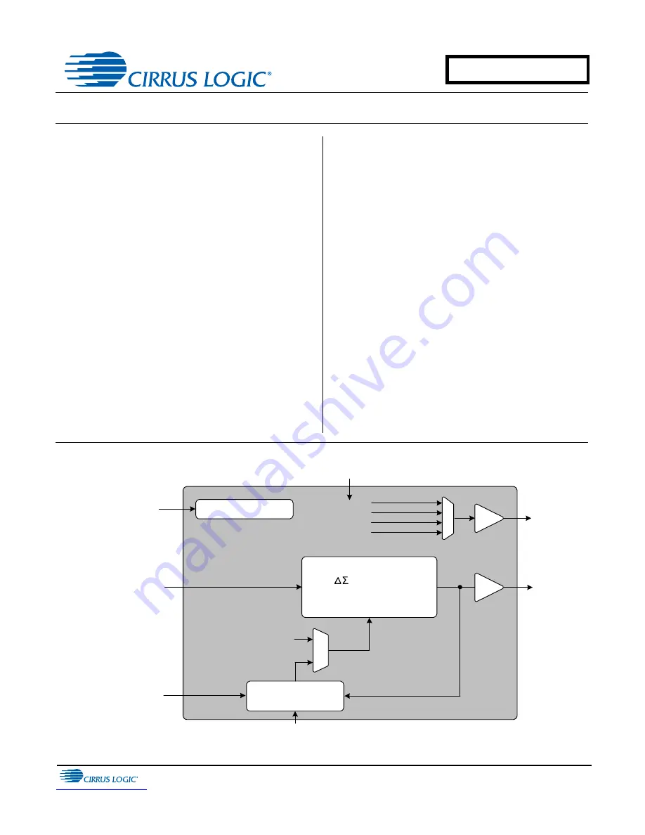
Fractional-N Clock Synthesizer & Clock Multiplier

Features

Delta-Sigma Fractional-N Frequency Synthesis

– Generates a Low Jitter 6 - 75 MHz Clock 

from an 8 - 75 MHz Reference Clock

Clock Multiplier / Jitter Reduction

– Generates a Low Jitter 6 - 75 MHz Clock 

from a Jittery 50 Hz to 30 MHz Clock 

Source

Highly Accurate PLL Multiplication Factor

– Maximum Error Less Than 1 PPM in High-

Resolution Mode

One-Time Programmability

– Configurable Hardware Control Pins
– Configurable Auxiliary Output

Flexible Sourcing of Reference Clock

– External Oscillator or Clock Source
– Supports Inexpensive Local Crystal

Minimal Board Space Required

– No External Analog Loop-filter 

Components

General Description

The CS2000-OTP is an extremely versatile system
clocking device that utilizes a programmable phase lock
loop. The CS2000-OTP is based on a hybrid analog-
digital PLL architecture comprised of a unique combina-
tion of a Delta-Sigma Fractional-N Frequency
Synthesizer and a Digital PLL. This architecture allows
for both frequency synthesis/clock generation from a
stable reference clock as well as generation of a low-jit-
ter clock relative to an external noisy synchronization
clock with frequencies as low as 50 Hz. The CS2000-
OTP has many configuration options which are set once
prior to runtime. At runtime there are three hardware
configuration pins available for mode and feature
selection.

The CS2000-OTP is available in a 10-pin MSOP pack-
age in Commercial (-10°C to +70°C) and Automotive-D
(-40°C to +85°C) and Automotive-E (-40°C to +105°C)
grades. Customer development kits are also available
for custom device prototyping, small production pro-
gramming, and device evaluation. Please see 

“Ordering

Information” on page 29

 for complete details.

Hardware Configuration

Auxiliary 

Output

6 to 75 MHz 

PLL Output

Frequency Reference

3.3 V

Hardware Control

8 MHz to 75 MHz

Low-Jitter Timing Reference

       Fractional-N 

Frequency Synthesizer

Digital PLL & Fractional 

N Logic

Output to Input 

Clock Ratio

N

Timing Reference

PLL Output
Lock Indicator

50 Hz to 30 MHz  

Frequency Reference

Output to Input 

Clock Ratio

OCT '15

DS758F3

CS2000-OTP

Summary of Contents for CS2000-OTP

Page 1: ...a Delta Sigma Fractional N Frequency Synthesizer and a Digital PLL This architecture allows for both frequency synthesis clock generation from a stable reference clock as well as generation of a low jit ter clock relative to an external noisy synchronization clock with frequencies as low as 50 Hz The CS2000 OTP has many configuration options which are set once prior to runtime At runtime there are...

Page 2: ...ective Ratio REFF 15 5 4 5 Fractional N Source Selection 15 5 4 5 1 Manual Fractional N Source Selection for the Frequency Synthesizer 16 5 4 5 2 Automatic Fractional N Source Selection for the Frequency Synthesizer 16 5 4 6 Ratio Configuration Summary 17 5 5 PLL Clock Output 18 5 6 Auxiliary Output 18 5 7 Mode Pin Functionality 19 5 7 1 M1 and M0 Mode Pin Functionality 19 5 7 2 M2 Mode Pin Functi...

Page 3: ...usoidal Jitter Transfer 8 Figure 4 CLK_IN Random Jitter Rejection and Tolerance 8 Figure 5 Delta Sigma Fractional N Frequency Synthesizer 9 Figure 6 Hybrid Analog Digital PLL 10 Figure 7 Fractional N Source Selection Overview 10 Figure 8 Internal Timing Reference Clock Divider 11 Figure 9 REF_CLK Frequency vs a Fixed CLK_OUT 12 Figure 10 External Component Requirements for Crystal Circuit 12 Figur...

Page 4: ...e Clock Input Input Clock input for the Digital PLL frequency reference XTO XTI REF_CLK 6 7 Crystal Connections XTI XTO Timing Reference Clock Input REF_CLK Input Output XTI XTO are I O pins for an external crystal which may be used to generate the low jitter PLL input clock REF_CLK is an input for an externally generated low jitter reference clock M2 8 Mode Select Input M2 is a configurable mode ...

Page 5: ...nce CLK_IN XTO CLK_OUT AUX_OUT 0 1 µF VD 3 3 V M0 Low Jitter Timing Reference System Microcontroller 1 µF 1 or 2 REF_CLK XTO XTI XTO or 40 pF x 40 pF Crystal To circuitry which requires a low jitter clock N C To other circuitry or Microcontroller Figure 1 Typical Connection Diagram CS2000 OTP ...

Page 6: ...tomotive E Grade Notes 4 To calculate the additional current consumption due to loading per output pin multiply clock output frequency by load capacitance and power supply voltage For example fCLK_OUT 49 152 MHz CL 15 pF VD 3 3 V 2 4 mA of additional current due to these loading conditions on CLK_OUT Parameters Symbol Min Typ Max Units DC Power Supply Note 2 VD 3 1 3 3 3 5 V Ambient Operating Temp...

Page 7: ...n Typ Max Units Crystal Frequency Fundamental Mode XTAL fXTAL RefClkDiv 1 0 10 RefClkDiv 1 0 01 RefClkDiv 1 0 00 8 16 32 14 28 50 MHz MHz MHz Reference Clock Input Frequency fREF_CLK RefClkDiv 1 0 10 RefClkDiv 1 0 01 RefClkDiv 1 0 00 8 16 32 14 28 56 MHz MHz MHz Reference Clock Input Duty Cycle DREF_CLK 45 55 Internal System Clock Frequency fSYS_CLK 8 14 MHz Clock Input Frequency fCLK_IN 50 Hz 30 ...

Page 8: ...dwidth 128 Hz Bandwidth 1 10 100 1000 10000 60 50 40 30 20 10 0 10 Input Jitter Frequency Hz Jitter Transfer dB 1 Hz Bandwidth 128 Hz Bandwidth Figure 2 CLK_IN Sinusoidal Jitter Tolerance Figure 3 CLK_IN Sinusoidal Jitter Transfer Samples size 2 5M points Base Band Jitter 100Hz to 40kHz Samples size 2 5M points Base Band Jitter 100Hz to 40kHz Figure 4 CLK_IN Random Jitter Rejection and Tolerance 0...

Page 9: ...frequencies without the need for external filter components As with any Fractional N Frequency Synthesizer the timing reference clock should be stable and jitter free Figure 5 Delta Sigma Fractional N Frequency Synthesizer 4 2 Hybrid Analog Digital Phase Locked Loop The addition of the Digital PLL and Fractional N Logic shown in Figure 6 to the Fractional N Frequency Synthesizer creates the Hybrid...

Page 10: ...Selection between these two modes can either be made automatically based on the presence of the Frequency Reference Clock or manually through the mode select pins Figure 7 Fractional N Source Selection Overview N Digital Filter Frequency Comparator for Frac N Generation Frequency Reference Clock Delta Sigma Fractional N Frequency Synthesizer Digital PLL and Fractional N Logic Output to Input Ratio...

Page 11: ...ed to a lower maximum frequency than that allowed on the XTI REF_CLK pin The CS2000 OTP supports the wider external frequency range by offering an internal divider for RefClk The RefClkDiv 1 0 global parameter should be configured such that SysClk the divided RefClk then falls within the valid range as indicated in AC Electrical Characteristics on page 7 It should be noted that the maximum allowab...

Page 12: ...ency Reference Clock Input CLK_IN The frequency reference clock input CLK_IN is used in Hybrid PLL Mode by the Digital PLL and Fractional N Logic block to dynamically generate a fractional N value for the Frequency Synthesizer see Hybrid An alog Digital PLL on page 10 The Digital PLL first compares the CLK_IN frequency to the PLL output The Fractional N logic block then translates the desired rati...

Page 13: ...fit from the maximum jitter and wander rejection of the lowest PLL bandwidth setting See Figure 11 Systems in which some clocks and data are derived from the PLL_OUT signal while other clocks and data are derived from the CLK_IN signal will often require phase alignment of all the clocks and data in the system See Figure 12 If there is substantial wander on the CLK_IN signal in these applications ...

Page 14: ...io based Hybrid PLL Mode is made with the M 1 0 pins unless auto fractional N source selection is enabled see section 5 4 5 on page 15 In addition to the High Resolution ratio format a High Multiplication format is also available In the High Multiplication format mode the 32 bit fixed point number for RUD is represented in a 20 12 format where the 20 MSBs represent the integer binary portion while...

Page 15: ...ncy limits for both the input and output clocks as shown in the AC Electrical Characteristics on page 7 Selection of the user defined ratio from the four stored ratios is made by using the M 1 0 pins unless auto clock switching is enabled in which case the LockClk 1 0 modal parameter also selects the ratio see Fractional N Source Selection on page 15 5 4 5 Fractional N Source Selection To select b...

Page 16: ...lk and re acquiring lock during which time the PLL is unlocked The modal ratio location see Table 1 on page 11 should contain the desired CLK_OUT to RefClk ratio to be used when CLK_IN is not present The User Defined Ratio pointed to by LockClk 1 0 should contain the desired CLK_OUT to CLK_IN ratio to be used when CLK_IN is present Auto matic source selection is enabled when the LockClk 1 0 modal ...

Page 17: ...features involved in the calculation of the ratio values used to generate the fractional N value which controls the Frequency Synthesizer The subscript 4 indicates the modal parameters Figure 13 Ratio Feature Summary Referenced Control Parameter Definition Ratio 0 3 Ratio 0 3 on page 23 M 1 0 pins M1 and M0 Mode Pin Functionality on page 19 LockClk 1 0 Lock Clock Ratio LockClk 1 0 section on page ...

Page 18: ...rder to indicate an unlock condition REF_CLK must be present If AUX_OUT is set to CLK_OUT the phase of the PLL Clock Output signal on AUX_OUT may differ from the CLK_OUT pin The driver for the pin can be set to high impedance using the M2 pin when the M2Config 1 0 global parameter is set to either 001 or 010 Figure 15 Auxiliary Output Selection Referenced Control Parameter Definition ClkOutUnl Ena...

Page 19: ...vailable options and the following sections will describe each option in more detail Figure 16 M2 Mapping Options 5 7 2 1 M2 Configured as Output Disable If M2Config 2 0 is set to either 000 001 or 010 M2 becomes an output disable pin for one or both output pins If M2 is driven low the corresponding output s will be enabled if M2 is driven high the corresponding output s will be disabled 5 7 2 2 M...

Page 20: ...If M2 is driven high the fractional N value will be the Dynamic Ratio sourced from the Digital PLL for Hy brid PLL Mode 5 7 2 5 M2 Configured as AuxOutSrc Override If M2Config 2 0 is set to 111 M2 when driven high will override the AuxOutSrc 1 0 modal pa rameter and force the AUX_OUT source to PLL Clock Output When M2 is driven low AUX_OUT will function according to AuxOutSrc 1 0 5 8 Clock Output ...

Page 21: ...on the Frequency Reference Clock CLK_IN Gradual changes in CLK_IN frequency greater than 30 from the starting frequency Step changes in CLK_IN frequency 5 9 Required Power Up Sequencing for Programmed Devices Apply power All input pins except XTI REF_CLK should be held in a static logic hi or lo state until the DC Power Supply specification in the Recommended Operating Conditions table on page 6 a...

Page 22: ... used as a factor in determining the PLL s Fractional N Note This parameter does not take affect unless M2 pin is high and the M2Config 2 0 global param eter is set to 011 RModSel 1 0 R Mod Selection 00 Right shift R value by 1 2 01 Right shift R value by 2 4 10 Right shift R value by 3 8 11 Right shift R value by 4 16 Application Ratio Modifier R Mod on page 15 M 1 0 pins Modal Configuration Set ...

Page 23: ...e for Frequency Synthesizer FracNSrc Selects static or dynamic ratio mode when auto clock switching is disabled 6 2 Ratio 0 3 The four 32 bit User Defined Ratios are stored in the CS2000 s one time programmable memory See Out put to Input Frequency Ratio Configuration on page 14 and Calculating the User Defined Ratio on page 26 for more details AuxOutSrc 1 0 Auxiliary Output Source 00 RefClk 01 CL...

Page 24: ... either manually or automatically see section 5 4 5 on page 15 Note When the static ratio based Frequency Synthesizer Mode is selected either manually or auto matically the currently indexed User Defined Ratio will always be interpreted as a 12 20 fixed point value regardless of how this parameter is set AuxLockCfg AUX_OUT Driver Configuration 0 Push Pull Active High output high for unlocked condi...

Page 25: ... 001 Disable AUX_OUT pin 010 Disable CLK_OUT and AUX_OUT 011 RModSel 1 0 Modal Parameter Enable 100 Force Manual Fractional N Source Selection 101 Reserved 110 FracNSrc Modal Parameter Override 111 Force AuxOutSrc 1 0 10 PLL Clock Out Application M2 Mode Pin Functionality on page 19 ClkIn_BW 2 0 Minimum Loop Bandwidth 000 1 Hz 001 2 Hz 010 4 Hz 011 8 Hz 100 16 Hz 101 32 Hz 110 64 Hz 111 128 Hz App...

Page 26: ...caled decimal representation then use the decimal to binary hex conversion function on a cal culator and write to the register A few examples have been provided in Table 3 Table 3 Example 12 20 R Values 7 2 High Multiplication 20 12 Format To calculate the User Defined Ratio RUD to store in the register s divide the desired output clock frequen cy by the given input clock CLK_IN Then multiply the ...

Page 27: ...2000 pro gramming and evaluation tools Below is a form which represents the information required for programming a device noted in gray The Parameter Descriptions section beginning on page 22 describes the functions of each parameter This form may be used ei ther for personal notation for device configuration or it can be filled out and given to a Cirrus representative in con junction with the pro...

Page 28: ... MAX A 0 0433 1 10 A1 0 0 0059 0 0 15 A2 0 0295 0 0374 0 75 0 95 b 0 0059 0 0118 0 15 0 30 4 5 c 0 0031 0 0091 0 08 0 23 D 0 1181 BSC 3 00 BSC 2 E 0 1929 BSC 4 90 BSC E1 0 1181 BSC 3 00 BSC 3 e 0 0197 BSC 0 50 BSC L 0 0157 0 0236 0 0315 0 40 0 60 0 80 L1 0 0374 REF 0 95 REF Parameter Symbol Min Typ Max Units Junction to Ambient Thermal Impedance JEDEC 2 Layer JEDEC 4 Layer JA JA 170 100 C W C W Ju...

Page 29: ...locking Device 10L MSOP Yes 40 to 105 C Tape and Reel CS2000P EZZR CDK2000 Evaluation Platform Yes CDK2000 CLK Release Changes F1 AUG 09 Updated Period Jitter specification in AC Electrical Characteristics on page 7 Updated Crystal and Ref Clock Frequency specifications in AC Electrical Characteristics on page 7 Added PLL Performance Plots section on page 8 Updated Internal Timing Reference Clock ...

Page 30: ...LLY IMPLANTED INTO THE BODY AUTOMOTIVE SAFETY OR SECURITY DEVICES NUCLEAR SYSTEMS LIFE SUPPORT PROD UCTS OR OTHER CRITICAL APPLICATIONS INCLUSION OF CIRRUS PRODUCTS IN SUCH APPLICATIONS IS UNDERSTOOD TO BE FULLY AT THE CUS TOMER S RISK AND CIRRUS DISCLAIMS AND MAKES NO WARRANTY EXPRESS STATUTORY OR IMPLIED INCLUDING THE IMPLIED WARRANTIES OF MERCHANTABILITY AND FITNESS FOR PARTICULAR PURPOSE WITH ...

Reviews: