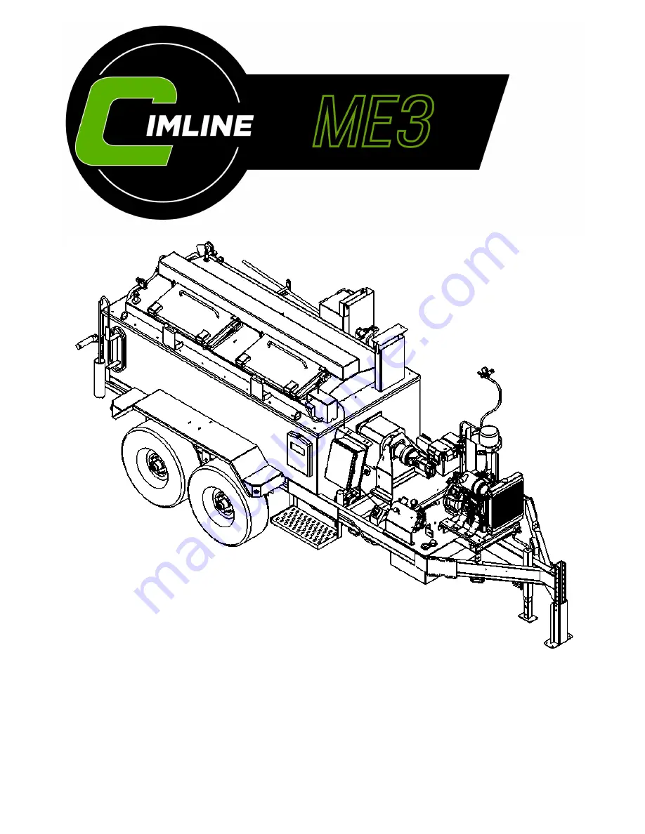
background image

Mastic Extruder 

Owner/Operator Manual  

Due to continuous product development some of the details shown in this manual may differ from 

your equipment. We reserve the right to change the contents of the manual without notification.  

CIMLINE.COM 

2601 Niagara Lane · Plymouth, MN  55447 · (763) 557-1982 · (877) 841-0848 · Fax (763) 557-1971 

  Part # 308-000-000     


                 REV B 06/8/21 


Summary of Contents for ME3

Page 1: ...nt some of the details shown in this manual may differ from your equipment We reserve the right to change the contents of the manual without notification CIMLINE COM 2601 Niagara Lane Plymouth MN 55447 763 557 1982 877 841 0848 Fax 763 557 1971 Part 308 000 000 REV B 06 8 21 ...

Page 2: ...ME3 Maintenance Heat Transfer Oil Servicing 26 27 ME3 Maintenance Tank Burner 28 31 ME3 Maintenance Trouble Shooting Guide 32 PARTS AND ASSEMBLY DRAWINGS ME3 Trailer Wiring Diagram and Parts 34 ME3 Main Wiring Harness 35 ME3 Control Panel Wiring Diagram and Parts 36 38 ME3 Tank Burner Internal Wiring Diagram 39 ME3 Tank Burner Parts 40 ME3 Agitation System Diagram and Parts 41 ME3 Hydraulic Manifo...

Page 3: ...ating to CIMLINE equipment should be directed to your local dealer FIRST CIMLINE Customer Care and Technical Service CIMLINE Technical Service is available Monday Friday during normal business hours Toll Free 877 841 0848 Telephone 763 694 2665 Fax 866 553 7765 www cimline com Email customercareorders plymouthind com CIMLINE Parts and Warranty Items Toll Free 800 328 3874 Telephone 763 694 2638 Fa...

Page 4: ...ke sure all lights are in working order and reflectors are clean d Properly secure any loose items found or stored on machine 2 Never go under trailer without first stabilizing trailer 3 Never touch material expelled by melter while still hot 4 Never leave machine unattended while it is running 5 Keep material door closed at all times except when adding material 6 Load melter from ground level 7 D...

Page 5: ...onal accessories or the weight of the sealant The weight of your trailer will vary weigh your machine to determining your Gross Vehicle Weight GVW Scales are sometimes available to use at state highway weigh stations refuse transfer stations and commercial truck stops Trailer Stabilizing Procedure Going under the trailer puts a person at risk of severe injury or death Follow procedure below to sta...

Page 6: ...uggested by manufacturer Failure to use correct rim contour may cause dramatic separation of tire and wheel and could cause serious injury or death Attempting to modify or repair a wheel can cause unsafe conditions that may result in an explosion Air pressure on a weakened or cracked rim can cause serious injury or death Torque Requirements It is extremely important to apply and maintain proper wh...

Page 7: ... NOT bleed air from tires when they are hot Check inflation pressure weekly during use to insure maximum tire and tread life The following tire wear diagnostic chart will help you pinpoint the causes and solutions of tire wear problems NOTE Tire wear should be checked frequently because once a wear pattern becomes firmly established in a tire it is difficult to stop even if the underlying cause is...

Page 8: ...8 Weight and Dimensions WEIGHT AND DIMENSIONS ARE FOR BASE UNIT WITHOUT OPTIONS WEIGHT LISTED DOES NOT INCLUDE MATERIAL WEIGHT Length 220 in 559 cm BASE WEIGHT 6500 lb 2954 kg ...

Page 9: ...ty 350 Gallons 260 Gallons Product specification may change without notice Images contained in this manual may differ from the actual product To maintain safe operation of trailer do not fill tank more than 75 of tank size WARNING Width 86 in 214 cm Height 75 in 191 cm ...

Page 10: ...10 Replacement Labels Inspect your labels and replace any damaged Contact your dealer to order replacement labels Part 308 278 000 ...

Page 11: ... to monitor the amount of Heat Transfer Oil in the tank Displays the heat transfer oil temperature 4 Mastic Trough Mastic is dispensed from the chute chute angle can be adjusted The Trough is heated with a propane burner 5 Mastic Gate Controls the mastic to flow or stop 6 Loading Door Place the material on safety door to load the melting tank 7 Control Panel The main control panel is used to monit...

Page 12: ...12 Control Panels Main Control Panel The control panel is used to operate the melter control system All controls are located within the cover ...

Page 13: ...13 Inside the Main Control Panel box is a Sub Control Panel See the next page for detailed explanation of use ...

Page 14: ... Oil has reached the preset temperature This indicates that you can turn the agitator on 5 Oil Temperature Controller The controller for your CIMLINE ME3 melter has been factory set to run ISO Grade 68 heat transfer oil 6 Material LED Green This LED indicates that the Material has reached the preset temperature 7 Material Temperature Controller The control system on your CIMLINE ME3 melter has bee...

Page 15: ...15 Sub Control Panel Controls and Their Functions 1 2 3 4 6 7 8 5 ...

Page 16: ... C Turn key to 2 Melter Start Up Load Material into Empty Tank All material must be clean Keep all foreign matter out of melting tank 1 Open the material door a and place the block of material b on the open door against the holder c 2 Push door to the closed position TO AVOID CONTACT WITH HOT SEALANT DO NOT DROP MATERIAL INTO THE MELTER WITH DOOR OPEN LOADING OPERATOR MUST WEAR PROTECTIVE CLOATHIN...

Page 17: ...e proper mixing Agitator speed can be observed by looking at the love joy coupling Use caution when in proximity to flowing hot material This includes proper face and skin protection CAUTION DO NOT OPERATE MACHINE IF DOOR ACTIVATED AGITATOR STOP IS NOT WORKING 5 Propane Burner Controls Needle Valve P 121163 Propane Orifice P 156392 A Open Propane Tank and set regulator to 15 PSI B Open ball valves...

Page 18: ...d the 3rd at the back of the machine on the passenger side and close the propane tank B Set Control Panel Main Panel switch to OFF Indicated by the Panel Power LED being unpowered C Put the agitator into the Heat Up position D Let machine run for 15 to 30 minutes E Put the Agitator Directional Switch to the OFF position APPLYING MASTIC With Start Up procedure complete you are ready to begin sealin...

Page 19: ...ing the directions below Decrease Increase A 1 Press the SET button 2 SP1 is displayed 3 Press the SET button 4 Current Temperature is displayed 5 Use the arrow buttons to change to the desired temperature 6 Press the SET button 7 Let the controller time out Your controller will now be changed and the updates will be saved Material Tank Capacity MATERIAL CAPACITY Tank cutaway MATERIAL VAT AIR OIL ...

Page 20: ...form to different applications YOU MUST CLARIFY with the supplier that the oil is to be used in a heat transfer system to avoid any potential problems Oil is also available from CIMLINE in 5 and 30 gallon 19 and 114L containers for ship out FLASH POINT Test in which an open container of oil is heated until an open flame will flash when passed over the fumes FIRE POINT Same test as the flash point ...

Page 21: ...petroleum based product CIMLINE recommends that you do not mix oil brands Mixing any oils Engine oil transmission fluid etc adversely affects each manufacturers formula ME3 Hydraulic Reserve Capacity 15 Gallons 114L Hydraulic Oil Type Conoco MV32 or equiv Diesel Fuel Capacity 30 Gallons 114L Diesel Fuel Type ASTM D975 No 2 Heat Transfer Oil Capacity 58 Gal 80L Heat Transfer Oil Type See Specs On P...

Page 22: ...e Schedule 23 ME3 Maintenance Key Components 24 ME3 Maintenance Changing Heat Transfer Oil 25 ME3 Maintenance Hydraulic Oil Servicing 26 27 ME3 Maintenance Tank Burner 28 31 ME3 Maintenance Trouble Shooting Guide 32 ME3 Maintenance And Troubleshooting ...

Page 23: ... GLAND X INSPECT PROPANE SYSTEM AND ORIFICES X SERVICE AIR CLEARNER ELEMENT GASGETS X INSPECT BURNER NOZZLE ELECTRODE AND HEAD POS ADJUST IF NECESSARY X CHANGE ENGINE OIL AND OIL FILTER X REPLACE FUEL FILTER X INSPECT DIESEL BURNER ELECTRIC EYE CLEAN IF DIRTY X GREASE WHEEL BEARINGS X INSPECT STARTER MOTOR X REPLACE HYDRAULIC OIL X REPLACE HYDRAULIC RETURN FILTER X REPLACE HYDRAULIC SUCTION STRAIN...

Page 24: ...nd from housing Reference engine manual for washing instructions CIMLINE recommends stocking replacement filters Fuel Use high quality detergent oil of API American Petroleum Institute service class CC or CD grade Select the viscosity based on the air temperature at the time of operation Reference your engine manual for other recommendations Burner This machine has a single burner There are severa...

Page 25: ... provided for checking heat transfer oil level when cold HEAT TRANSFER OIL LONGEVITY The regular interval for changing heat transfer oil is once annually or every 500 hours If the time frame between heat transfer oil changes is not known a significant difference in temperature from the digital oil controller readout and the analog gauge may mean the oil has reached it s service life and is due to ...

Page 26: ...k test them before filling the tank completely with hydraulic oil 8 Reassemble the return filter assembly in reverse of the disassembly instructions being careful to not drop the filter cup O ring B into the tank while replacing the filter cup A into the return filter base 9 Spin on a new filter cartridge B 10 Fill the tank using high quality Conoco MV32 or equivalent hydraulic oil The maximum cap...

Page 27: ...or equivalent hydraulic oil CIMLINE recommends that you do not mix oil brands Mixing any oils Engine oil hydraulic oil etc adversely affects each manufacturers formula The maximum capacity of the hydraulic reserve tank is 15 gallons 125L HYDRAULIC OIL CAPACITY The maximum capacity of the hydraulic tank is 15 gallons but the actual fill level of hydraulic oil is between 12 and 13 gallons Do not fil...

Page 28: ...h one having the exact specifications from CIMLINE E Clean and inspect the electrodes for damage replacing any that are cracked or chipped F Check electrode tip settings Replace electrodes if tips are rounded G Inspect the igniter spring contacts Clean or replace if corroded H Clean the cad cell electric eye if applicable I Inspect all gaskets including the igniter base plate gasket Replace any th...

Page 29: ...or sufficient fuel pressure Pressure is 140 psig with valve energized Check the pump pressure Check for air in fuel lines Check burner for broken motor coupling If the coupling is broken check pump rotation prior to replacing the coupling Check for contaminated fuel and or partially plugged fuel filter Motor Not Operating If the blower motor is not operating check the following possibilities Check...

Page 30: ...off power to the burner B Disconnect the diesel fuel connector tube from the nozzle line C Loosen the two screws securing the igniter retaining clips a and rotate both clips to release the igniter baseplate Then tilt the igniter back on its hinge D Remove the splined nut b E Remove the nozzle line assembly from the burner being careful not to damage the electrodes or insulators while handling To e...

Page 31: ...ain sensed by the cad cell Air Supply Set up The tank burner is set up properly from the factory Air Band Position A should be set to 1 Shutter Position B should be set to 6 Motor Blower Wheel and Coupling Replacement See page 48 for the tank burner parts exploded view A Before servicing turn off and or disconnect all power to the burner B Disconnect the burner motor wires C Remove the bolts secur...

Page 32: ...Fuse burned out Check fuse Sealant material not hot enough Allow material to heat longer Too many biscuits added at one time Continue heat up and reverse agita tion to break biscuits free Low hydraulic oil level Check oil level Worn agitator motor Replace motor Sealant heat up time slow Burner orifice clogged Remove orifice and clean Heat transfer oil is worn out Check oil level Replace if necessa...

Page 33: ... and Parts 36 38 ME3 Tank Burner Internal Wiring Diagram 39 ME3 Oil Burner Parts 40 ME3 Agitation System Diagram and Parts 41 ME3 Hydraulic Manifold Parts and Schematic 42 43 ME3 Hydraulic Schematic and LP Component Breakdown 44 45 ME3 Diesel Engine Components 46 47 ME3 Miscellaneous Components and Parts 48 49 ME3 Mastic Tools 50 ...

Page 34: ...34 Trailer Wiring Diagram ...

Page 35: ...AL TANK BURNER BATTERY LOFA Engine Switch DESCRIPTION COLOR 1 BURNER POWER RED BLACK STRIPE 2 BATTERY RED 3 BURNER ENABLE WHITE 4 MICROPANEL ASSC PINK 5 BATTERY GREEN YELLOW STRIPE 30 BURNER ERROR BROWN ME3 MAIN HARNESS PN 308 242 000 Wiring diagram ...

Page 36: ...36 ME3 Control Panel Wiring Diagram BURNER STROBE HARNESS ME3 MASTIC WIRE HARNESS THERMOCOUPLES Part 130097 131057 AGITATOR STOP HARNESS Part 308 275 000 ...

Page 37: ...GE FUSE TO PANEL SWITCH 16 12 ORANGE PANE SWITCH TO CONTROLLERS 16 13 WHITE MATERIAL CONTROLLER TO MATERIAL TEMP 16 14 RED BLACK STRIPE MATERIAL CONTROLLER TO MATERIAL TEMP 16 15 WHITE OIL CONTROLLER TO OIL TEMP 16 16 RED BLACK STRIPE OIL CONTROLLER TO OIL TEMP 16 17 PURPLE MATERIAL CONTROLLER TO LED 16 18 GRAY OIL CONTROLLER TO MATERIAL CONTROLLER 16 19 PINK MATERIAL CONTROLLER TO BURNER RELAY 16...

Page 38: ...T E ME3 CONTROL PANEL B 200597 CONTROLLER MATERIAL C 200596 CONTROLLER OIL D 130625 GREEN LED LIGHT E 130831 FUSE BLOCK F 130227 SWITCH SPDT G 130222 PANEL RELAY H 130113 BURNER RELAY I 153870 RELAY BASE J 130624 AMBER LED LIGHT K 130831 LUG M 131036 VOLTMETER ...

Page 39: ...39 Burner Internal Wiring Diagram ...

Page 40: ...ER 5 155001 PUMP OIL 6 152106 ELECTRODE ROD INS ASSY 7 152128 GASKET BURNER FLANGE 8 152173 IGNITION TRANSFORMER ASSY 9 152200 OIL VALVE 10 200352 PRIMARY CONTROL ASSY 11 120443 AIR TUBE 12 120466 BURNER HEAD TUBE 13 152398 AIR INLET GUIDE 14 152399 COUPLING 15 152466 BLOWER WHEEL 16 152105 ELECTRIC EYE ASSY 130166 FUEL PRESSURE GAUGE NOT SHOWN ...

Page 41: ...ASHER 7 100858 HHCS 5 8 X 1 3 4 8 111946 GEARBOX 9 111947 COUPLING 2 25 DIA KEYED 10 111948 COUPLINE 2 38 11 111949 COUPLING INSERT 12 172687 HYRAULIC MOTOR 13 111950 AGITAOR BEARING 14 308 138 000 PLATE COUPLER SUPPORT 15 308 139 000 TUBE COUPLER 16 111950 PILLOW BLOCK BEARING 2 5 17 308 251 004 BEARING SHIELD 156443 1 2 PACKING ROPE FRONT 156444 3 8 PACKING ROPE REAR NOT SHOWN 16 17 ...

Page 42: ... SPINDLE 1 7 172694 3 WAY HYDRAULIC CONTROL VALVE 1 308 239 000 HYD HOSE KIT 1 8 12MP X 8FJS STR 1 9 12MJ X 12MP STR 1 10 8MJ X 8MP STR 2 11 8FJ X 6MJ STR 1 12 12MJ X 6MB STR 1 13 8MJ X 12MB STR 1 14 6MB X 8FJS STR 1 15 6MB PLUG 1 16 12MJX 12FJS 90 ELBOW 1 17 8MJ X 8FJS STR 1 18 4FP X 6FJS STR 1 19 8MJ X 8FJS X 8MJ TEE 2 20 12FJS X 12MJ X 12MJ TEE 1 21 8FJS X 8MJ X 8MJ TEE 1 22 12MJ X 12MB 90 ELBO...

Page 43: ...43 Mastic Hydraulic Manifold Components ...

Page 44: ...44 Hydraulic Schematic ...

Page 45: ...5 SWIVEL 4MP X 4MP 4 6 40 LP HOSE 40 7132 2534 101HY 4 4 101HY 4 4 2 7 115 LP HOSE 104 7132 2534 101HY 4 4 101HY 4 4 1 8 192 LP HOSE 192 7132 2534 101HY 4 4 101HY 4 4 1 9 120 LP HOSE 120 7132 2534 101HY 4 4 101HY 4 4 1 10 ELBOW 90 4MP HOSE X 4FP 1 11 ELBOW 90 4FP HOSE X 4MP 1 12 NIPPLE HEX 4MP 4MP 1 130006 REGULATOR 1 LP Component Breakdown NOT SHOWN ...

Page 46: ... 111951 ENGINE 3CJ1 ME3 2 308 252 004 PLATE ME3 ENGINE MOUNT 3 153619 MUFFLER COWL 4 172688 PUMP HYD 5 200543 BATTER BOX 6 152047 SEALANT ISOLATOR 7 111108 LOFA CONTROL SWITCH 8 150212 BATTER 26 26R 50 WET 9 111111 AIR FILTER 10 111337 OIL FILTER 11 155266 IGNITION KEY 12 111372 FAN BELT 13 111730 EXHAUST ELBOW ...

Page 47: ...47 Engine Components ENGINE MAINTENANCE KIT PART NUMBER 406599 PART DESCRIPTION 172695 SPIN ON FILTER 170169 FUEL FILTER BURNER 111457 FUEL FILTER ENGINE 111111 AIR FILTER 111337 OIL FILTER ...

Page 48: ...ARE 1 16 140731 WHEEL ST235 85R16 4 17 155894 CARABINER 2 18 156036 CHAIN 4 0 X 38 LINKS 1 19 156394 HANHELD LP TORCH 1 20 156395 SPRING ME3 1 21 308 251 004 PLATE COUPLING PROTECTION 1 22 308 274 000 HOSE OVERFLOW 1 23 308 317 004 THERMOCOUPLE PROTECTION WELD 1 130097 OIL THERMOCOUPLE 1 131057 MATERIAL THERMOCOUPLE 1 24 308 325 004 BURNER MOUNT WELD 1 25 308 117 004 GATE WELD 1 26 308 122 004 OUT...

Page 49: ...49 Miscellaneous Parts 28 29 30 30 ...

Page 50: ...rag box 304 071 004 16 in Width x 16 in Depth Mounted drag box to ease filling of longer cracks running the length of the road D Tank Scraper 308 326 004 Tool to help facilitate the cleaning of the material tank E Trough Scrapper 308 287 004 Standard with every ME3 Pulls material down material chute and trough F Mounted 30 in Drag box 304 072 000 30 in Width x 16 in Depth Mounted drag box to ease ...

Page 51: ......

Page 52: ...52 2601 Niagara Lane Plymouth MN 55447 763 557 1982 800 328 3874 Fax 763 557 1971 ...

Reviews: