Christie Mirage DS+10K-M2, User Manual
The Christie Mirage DS+10K-M2 is an exceptional projector designed for mesmerizing visual experiences. Unlock its full potential by accessing the comprehensive User Manual, available for download on our website. With a simple click, users can easily obtain this manual free of charge, ensuring smooth operation and optimal performance. Get yours now at manualshive.com.
Share
Download


Reviews:
No comments
Related manuals for Mirage DS+10K-M2

PT-RZ470EAW
Brand: Panasonic Pages: 138

W1110s
Brand: BenQ Pages: 64

MOP 900
Brand: Monster Power Pages: 5

MobiShow
Brand: 3M Pages: 8

2100
Brand: 3M Pages: 37

SC100
Brand: LG Pages: 12

PL-F860
Brand: LG Pages: 20
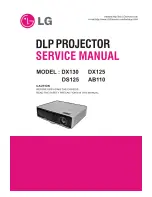
AB110
Brand: LG Pages: 66
3828VA0531D
Brand: LG Pages: 44

RT-52
Brand: LG Pages: 52

44/52SZ8R
Brand: LG Pages: 52

AU810PW-EU
Brand: LG Pages: 169

LAEC015-GN
Brand: LG Pages: 57

AN110B
Brand: LG Pages: 33

44SZ51D
Brand: LG Pages: 36
LSAA012-MX
Brand: LG Pages: 32

RT-44/48/52SZ50LP
Brand: LG Pages: 47

AH115
Brand: LG Pages: 33


